Introduction
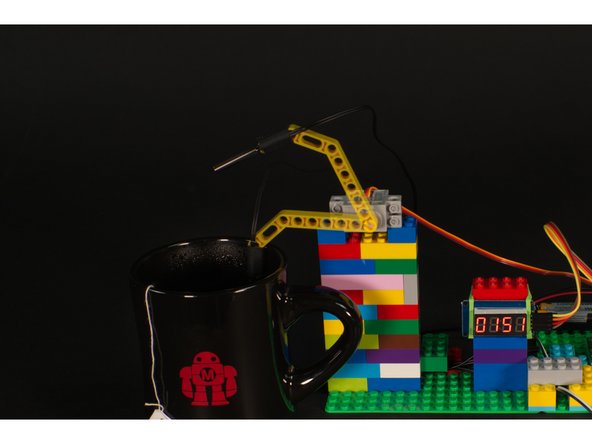
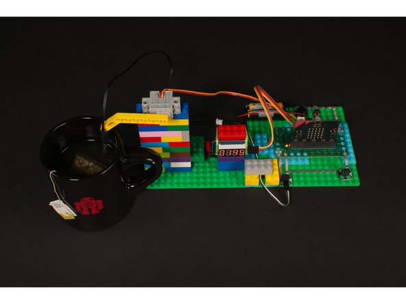
Connect a thermistor to a micro:bit so you can tell when you hot beverage has cooled down enough to enjoy.
Video Overview
Featured Document
-
-
A thermistor is a special kind of resistor whose resistance is dependent on temperature. The word thermistor is a combination of thermal and resistor. Thermistors are commonly used as temperature sensors, and often encased within a metal shell so they can withstand high temperatures.
-
Some thermistors decrease resistance when the temperature increases (these are called NTC or “Negative Temperature Coefficient”) and some increase resistance when the temperature increases (these are called PTC or “Positive Temperature Coefficient”).
-
Sometimes you'll see a thermistor called a "Temperature Probe" which is a good description, and it's how this project will be using a thermistor.
-
You can find a 10 pack of thermistors from Amazon or a single one from Adafruit.
-
Note: Make sure your thermistor has just two wires and not three, as the connection method will be different.
-
-
-
In the next few steps we'll build our circuit and connect everything to the Bit Board.
-
Once we've got all the parts in place and we program the micro:bit we'll need to determine the correct servo angles. It's not too difficult, but it's an extra step we need to get right.
-
Gather up all of your components, some 1/8" Maker Tape and some LEGO parts and we'll get started!
-
We won't detail the LEGO build for this project, but basically you'll need to build up bricks on a baseplate to hold the servo and other components in place.
-
The attached PDF has the full circuit diagram and other useful information about this project and how the thermistor works using a voltage divider.
-
-
-
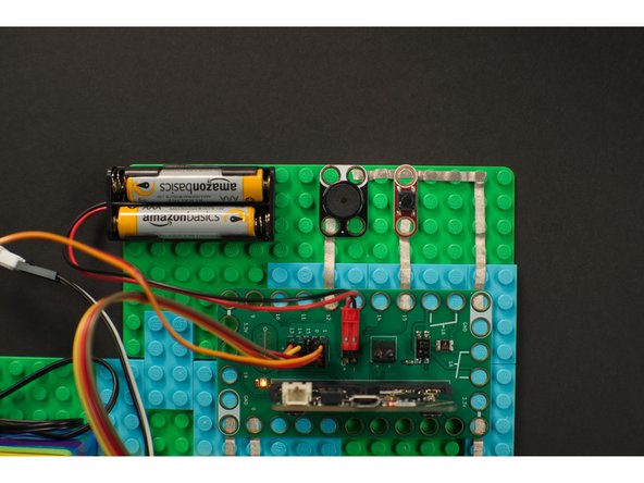
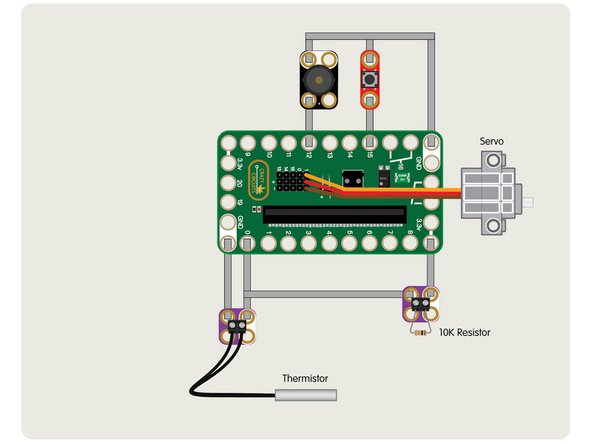
We'll first add a pushbutton and a piezo speaker as shown.
-
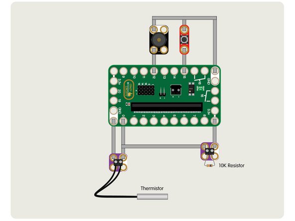
Our pushbutton connects to Pin 15 and ground, and when pressed starts the process of checking the temperature of our drink.
-
Our piezo speaker connects to Pin 12 and ground and will play a little song when our drink has reached the proper temperature.
-
Typically most of our components connect to a pin and to ground. In this case the button is an input and the micro:bit can tell when the button is pressed because it completes the circuit.
-
In the case of the piezo speaker it is an output and when it produces sound it's because current is flowing through the pin it is connected to and ground.
-
-
-
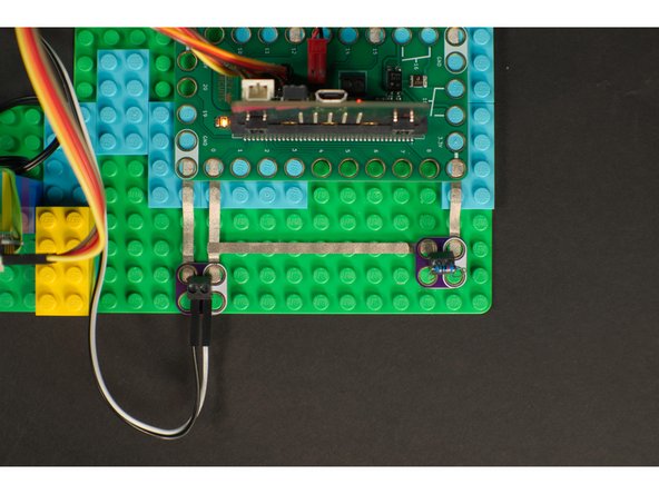
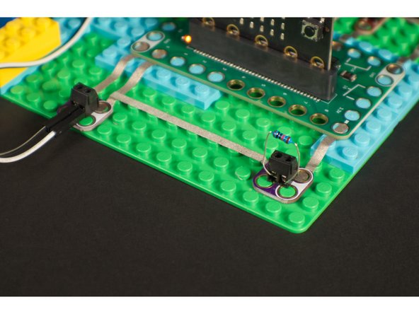
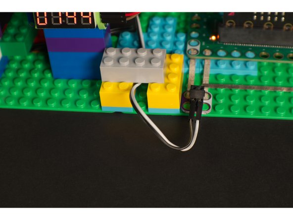
Our thermistor came with a small female connector at the end. We could have cut it off and stripped the wires to insert into the screw terminal, but we found some male jumper wires and used those instead.
-
You could also use some short pieces of solid core wire. Just strip a few millimeters of insulation off each end so the bare wire is exposed.
-
The resistor can be put right into the screw terminal. No cutting or stripping wires needed, no extra parts required. (You will need a small slotted screwdriver though.)
-
Since both parts are resistors, polarity does not matter. Unlike an LED which has a positive side and a negative side and allows current to flow in only one direction, parts with no polarity cannot be connected backwards.
-
You may notice that there is a connection between one side of the resistor that connects to a piece of tape that also runs between the thermistor and Pin 0. We'll examine that next!
-
-
-
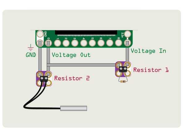
The pins on the micro:bit cannot read the resistance of a component, but they can read how much voltage is flowing through a circuit. We can read the value of our thermistor by using a voltage divider to flow current through the circuit, and then read the amount of voltage that is let through using an analog pin on the micro:bit.
-
Here's the schematic for a voltage divider that uses two resistor to “divide” the voltage. The way it works is similar to a potentiometer, where voltage flows through the component and the output is affected by a specific amount of resistance.
-
With a potentiometer you can rotate the knob to adjust the amount of resistance (which affects the amount of voltage output at the “Voltage Out” part of the circuit, or on a potentiometer the “center” pin). For our thermistor the temperature is what affects the resistance.
-
-
-
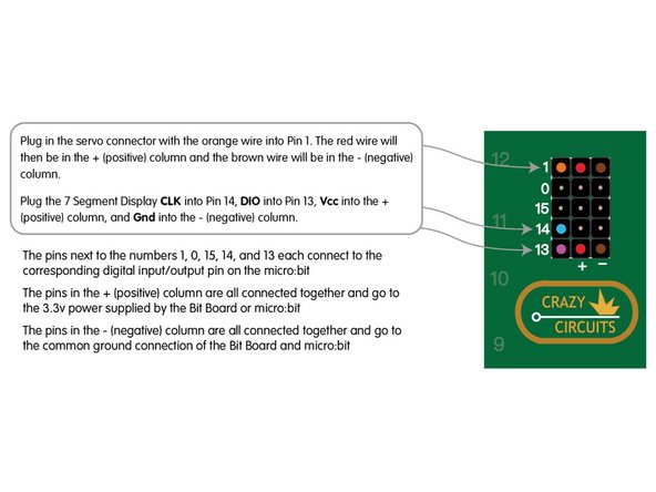
The servo has a three wire connection. The red wire is positive, the brown wire is negative (or ground) and the orange wire is the signal wire.
-
The red and brown wires are used to provide power to the servo, and the orange wire carries the "signal" from the micro:bit that tells the servo what to do.
-
The servo has all three wires together in a connector that plugs right into the pin headers on the Bit Board. Just make sure you plug it in the right way or your servo won't work!
-
-
-
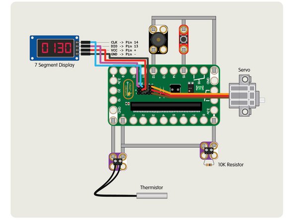
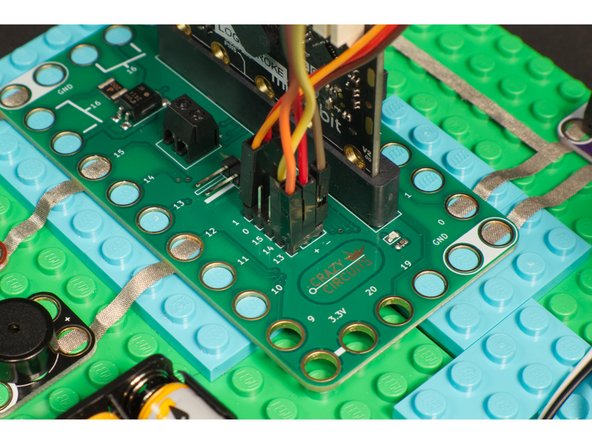
We'll add the 7 Segment Display by using four Female/Female jumper wires.
-
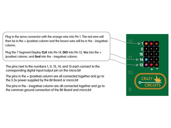
Plug the 7 Segment Display CLK into Pin 14, DIO into Pin 13, Vcc into the + (positive) column, and Gnd into the - (negative) column.
-
You can use any color wire you want, as long as they connect to the correct pin. It's common to use red for positive and black for negative but your circuit won't know what color the wires are. :)
-
The pins next to the numbers 1, 0, 15, 14, and 13 each connect to the corresponding digital input/output pin on the micro:bit
-
The pins in the + (positive) column are all connected together and go to the 3.3v power supplied by the Bit Board or micro:bit
-
The pins in the - (negative) column are all connected together and go to the common ground connection of the Bit Board and micro:bit
-
-
-
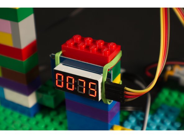
We want our 7 Segment Display mounted in such a way that we can easily see it and read the temperature.
-
We mounted ours by just stacking up some LEGO bricks and holding it in place with a rubber band, but you can get elaborate and build with more LEGO if desired.
-
-
-
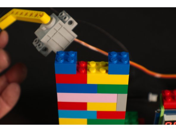
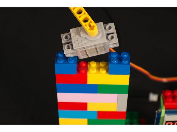
We needed to mount our servo at the proper height so it could lower the thermistor into our mug. This is easy to do with, you guessed it, LEGO bricks!
-
We just made a vertical stack. The nice thing about this simple method is that you can easily make it taller or shorter by just changing how many bricks you use.
-
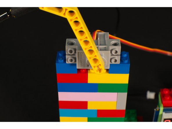
The LEGO compatible servo has holes that allow it to mount on its side and connect right to the studs on LEGO bricks.
-
-
-
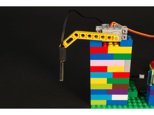
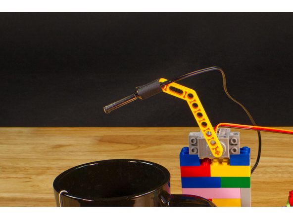
We're using a LEGO Technic Beam 3 x 3.8 x 7 Beam Bent 45 Double (32009 / 41486) which mounts to the servo shaft and is long enough to dip into our drink.
-
Our thermistor is attached to the Technic Beam using... tape! Yes, tape and rubber bands are always good to have on hand for making anything LEGO compatible!
-
The great thing about LEGO is that there are so many parts! If you don't have the same part we used, you can probably build something else that will work.
-
You may recognize this Technic Beam from our Bubble Blower project. It's come in handy a few times, so consider getting some from BrickOwl for future builds: https://www.brickowl.com/catalog/lego-te...
-
-
-
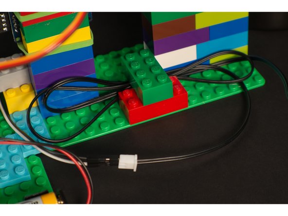
This step is completely optional, but some people really appreciate good wire routing. (Just do a search for "cable management" and you'll see what we mean!)
-
Depending on how you build with LEGO you may have wires running in multiple directions. We just used a few standard bricks to "capture" them and hold them in place.
-
For more permanent projects zip ties and hot glue are sometimes used to secure wire in place and prevent them from being pulled loose. For any of our projects we love using tape, rubber bands, and LEGO bricks. They work great!
-
-
-
Connect a USB cable to the micro:bit and then plug it into your computer.
-
We'll be using makecode.microbit.org to program our board. It uses a simple drag and drop block interface.
-
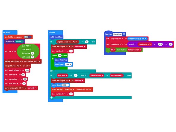
We're going to load the following code for our Hot Drink Checker program: https://makecode.microbit.org/_7zxczqJfo...
-
We're almost ready! We've got one more thing to do now that the code is loaded, and that's determine our servo angles. We'll do that in the next step.
-
-
-
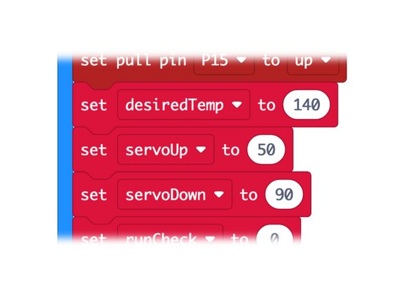
In our code we have a few variables we may need to adjust. First, you'll want to set your desired beverage temperature. You can change the desiredTemp to something besides 140 if you want.
-
What is a variable? Variables are used to store information to be referenced by a computer program. Some variables change during a program, and some are static and never change. We set these three variables at the start so you can easily change them if needed.
-
You may need to adjust the servoUp and servoDown values as well. Once you have the code loaded the servo will raise the arm, and when you press the button the servo will lower the arm. Adjust the two values until the servo goes to positions that work for up and down.
-
You can also pull off the Technic Beam, rotate it 90 degrees and reattach it. Since the beam is a small + shaped axle, it's a quick way to get your servo positioning close to what you want.
-
We wrote an entire guide on the LEGO Compatible 270 Degree Servo. If you want to dig in more, check it out!
-
-
-
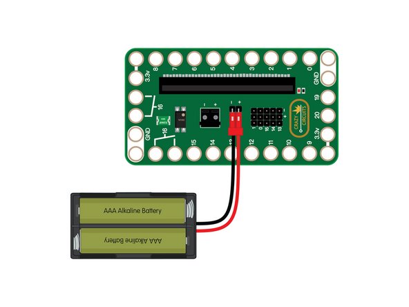
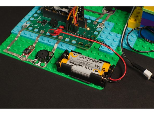
We're almost ready to try it out! Since this project uses a servo you'll want to plug in a battery pack to provide 3 volts to the Bit Board, which will provide the power needed to get our servo moving.
-
If you have a micro:bit V2 the servo may work with just a USB cable connected to the micro:bit, but we always recommend an external battery pack, which is required if you are using a V1.x micro:bit
-
-
-
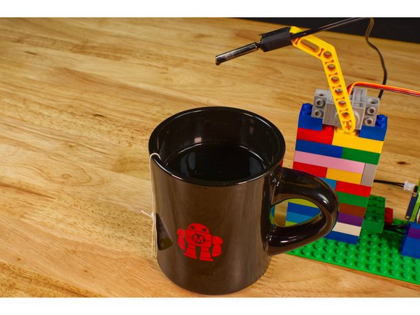
Grab yourself a steaming mug of your favorite drink and get ready to test things out!
-
When you power on the circuit the servo arm should move to the up position, and when you press the button it should lower down into your drink.
-
It will take a bit of time for the thermistor to read the temperature of your drink. We added a loop that will run for 30 seconds once the thermistor is lowered. It will check the temperature, wait one second, and then do that 29 more times.
-
After the initial 30 seconds the code will continually check the temperature every second and keep updating the 7 Segment Display as it does. When it reaches your desired temperature the servo will lift the arm and the piezo speaker will play a tune.
-
-
-
Like all of our projects, this should be considered a starting point from where you can change or extend things.
-
If you don't want to use a 7 Segment Display you could use a few LEDs to indicate temperature. Or if you want to make it more complex you could add an OLED Display.
-
Maybe instead of pressing a button you could add an Ultrasonic Distance Sensor that starts the process when you place a mug in front of it.
-
Also, be careful when working with hot liquids which can burn you, and be careful with any liquids around electronics projects!
-


