Tools
Parts
- micro:bit
- Crazy Circuits Bit Board
- Brick Compatible 270 Degree Servo
- AAA Batteries × 2
- 2 AAA Battery Holder
- Distance Sensor
- Crazy Circuits Ribbon Cable
- LEGO Baseplate
- LEGO 2x4 plate × 9
- Lego Technic Brick 1x8 with holes × 3
- LEGO Angle Connector #2 (180º) (32034 / 42134) × 6
- LEGO Bracket 2 x 2 - 2 x 2 Up (3956 / 35262) × 9
- LEGO Bracket 1 x 2 with 2 x 2 (21712 / 44728) × 2
- 1x4 LEGO plate (3710)
- LEGO Brick 1 x 2 with Bottom Tube (3004 / 93792)
- LEGO Brick 1 x 2 with Axle Hole (32064) × 2
- LEGO Bevel Gear with 12 Teeth (32270) × 2
- LEGO Half Bushing (32123 / 42136)
- LEGO Axle 4 with End Stop (87083) × 2
- LEGO Axle 10 (3737) × 2
- LEGO Axle Connector (Smooth with ‘x’ Hole) (59443)
- LEGO Gear Rack 14 (32185)
- LEGO Cross Block 1 x 3 (42003 / 42796) × 4
- LEGO Cross Block 1 x 3 with Two Axle Holes (32184 / 42142) × 3
- Printable Template
Featured Document
-
-
The grey brick-compatible 270 servo will be mounted atop and at a 90 degree angle from a simple tower to give it the height it needs to spin from in order to drive the gear rack upward enough for the desired end effect.
-
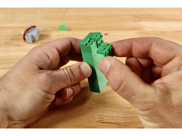
Stack 8 (2x4) bricks on top of one another. Then complete the top of the tower by connecting the two right angle brackets to one long side and the (1x4) plate in the space that remains. The tower should now have a (2x4) cluster of studs oriented outward when the tower is stood upward.
-
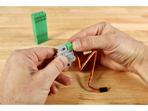
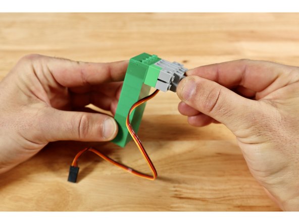
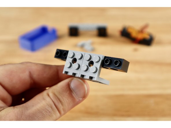
Connect the single (1x2) brick to either of the two recessed areas on the servo then connect the servo to the (2x4) cluster outward-facing studs on the tower. This orients the servo axle in the correct way to interact with the long straight gear that will eventually move your leprechaun upward.
-
-
-
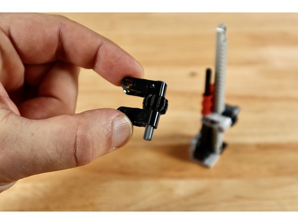
To begin the gear rack build, connect each of the (1x2) bricks with axle hole to a (2x2) 90 degree bracket as shown. Seat each of the long axles into the axle holes of the (1x2) bricks.
-
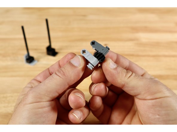
Now use 2 (1x3) cross blocks, one small axle with end stop, 1 (12 tooth) bevel gear and a half bushing to create the build in slide 2. The bevel gear should spin freely between the two cross blocks and the axle should be secured on one side with the half bushing.
-
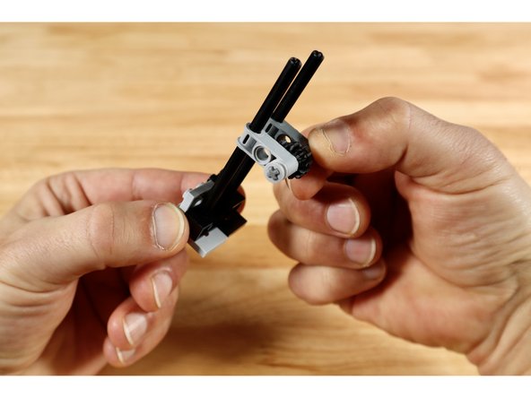
Seat each of the long axle ends from the first part of the build into the axle holes of the beveled gear build and slide it all down toward the bottom brackets.
-
-
-
Now slide 2 of the (1x3) cross blocks with two axle holes down on top of those same two long vertically oriented axles until they touch the cross block below.
-
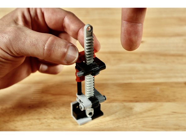
Insert the gear rack into the space behind the bevel gear so the teeth from both gears are facing one another and the smooth side of the gear rack is facing the 2 axle hole cross blocks behind it.
-
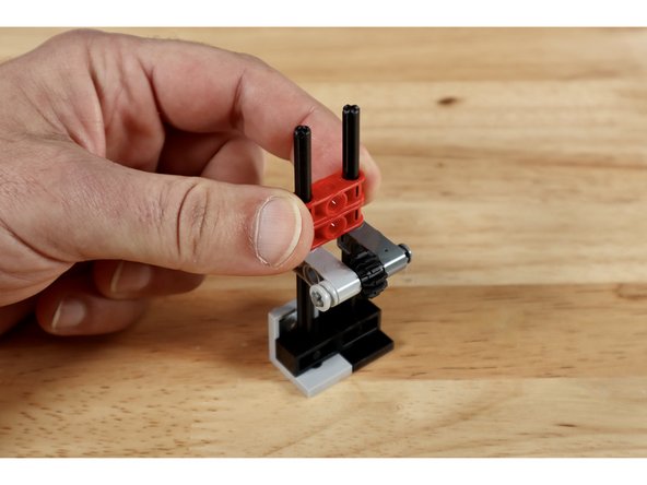
Now use the 2 remaining (1x3) cross blocks, small axle with end stop, and (12 tooth) bevel gear to create the build in slide 3. The bevel gear should spin freely between the two cross blocks and, unlike the similar cluster of parts below, the axle should be unsecured on one side.
-
-
-
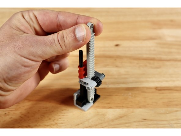
Guide the top of the gear rack through the space behind the bevel gear of the latest build and then seat the axle holes into the tops of the two tall axles. Slide this portion down the axles until they meet the rest of the cross blocks below.
-
Note: Add one more 1x3 cross block with 2 axle holes on top. It is pictured in slide 1 but not the remainder as this was an improvement made after the other photos were taken.
-
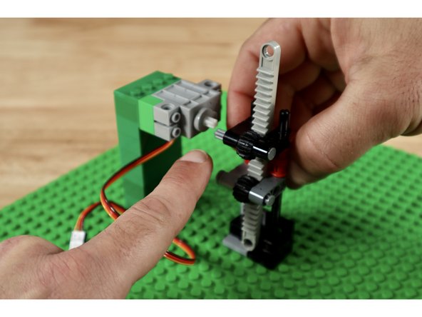
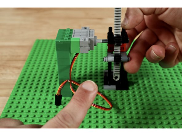
The servo axle will need to connect to the free end of the topmost axle during final assembly. You will need to adjust its height. To do this, pick any spot on the base plate and connect the servo tower. Then connect the gear rack right next to it. This will help you gauge the height of the two axles that need to be level with one another.
-
Slide the entire cross block part of the gear rack build up or down the tall axles until the upper axle is level with the one on the servo. Carefully disconnect the tower and rack builds and set them aside.
-
-
-
Note: This step relates to our brick-compatible 3D printed Distance Sensor Mount included in some kits. If you don't have one, you can either skip this assembly OR print your own using the linked file.
-
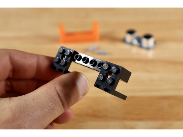
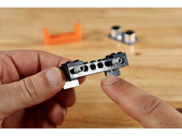
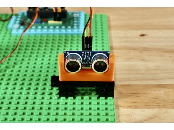
Connect 2 of your (2x2) 90 degree brackets to the outside edges of a (1x8) technic brick with holes to create the build shown in slide 1.
-
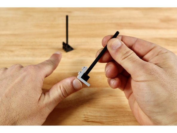
Press two connector pins into place in the holes of the (1x8) brick as shown. There should be 4 empty holes left between these pins on the (1x8) brick.
-
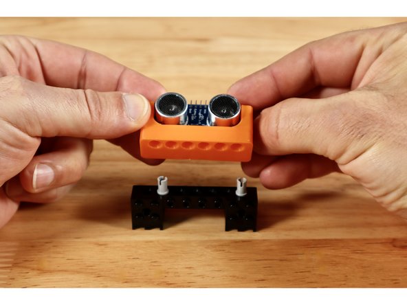
Connect your Distance Sensor Mount to the two pins as shown.
-
-
-
Note: This step relates to our brick-compatible 3D printed 2AAA Battery Pack Mount included in some kits. If you don't have one, you can either skip this assembly OR print your own using the linked file.
-
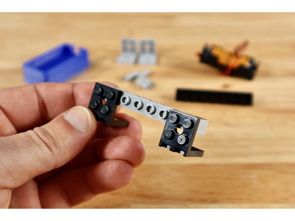
Connect 2 of your (2x2) 90 degree brackets to the outside edges of one of your 2 remaining 1x8 bricks with holes to create the build shown in slide 1.
-
Connect 2 more of your (2x2) 90 degree brackets to your last 1x8 brick with holes to create the build shown in slide 2. These brackets should occupy the 4 middle studs of the 1x8 brick with holes.
-
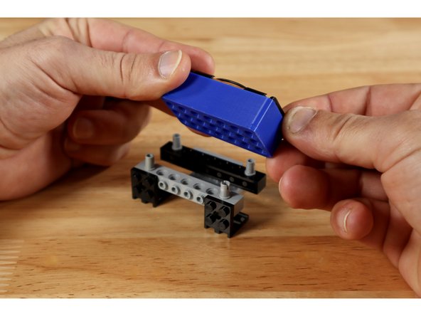
Press 1 connector pin into each of the corner holes on each of the (1x8) bricks; mounting the Battery Holder on top afterward as shown in slide 3.
-
-
-
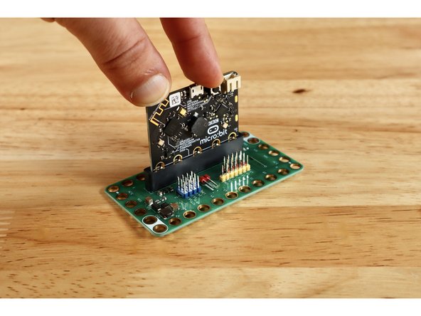
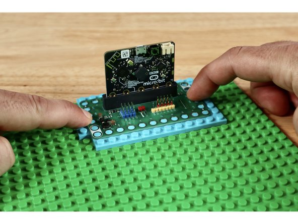
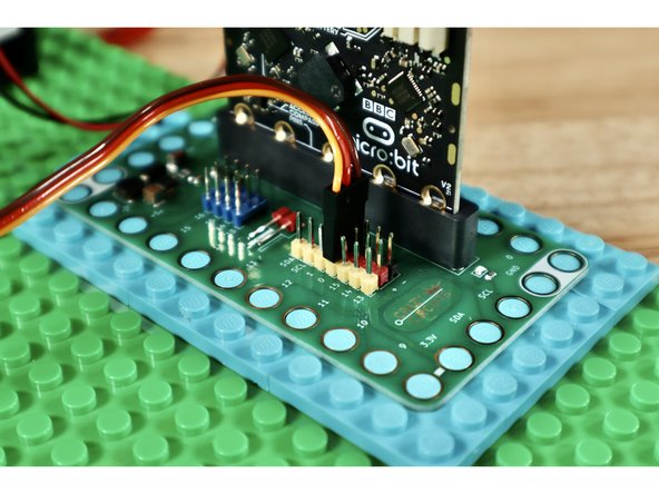
Insert your Micro:Bit into the Bit Board as shown.
-
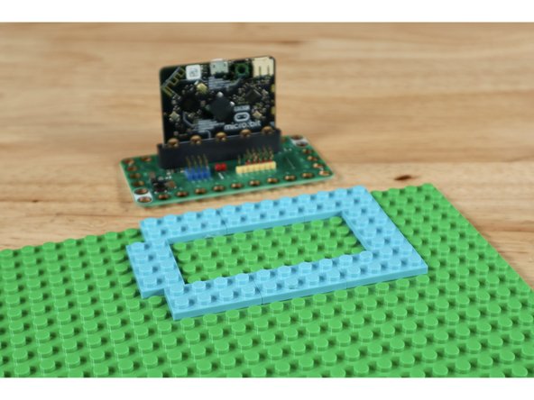
Use 8 (2x4) plates to create the arrangement shown on your base plate. It should be located somewhere along an edge of the base plate to afford ample room for final spacing of the remaining project parts.
-
Press your Bit Board into place atop the arrangement of plates as shown.
-
-
-
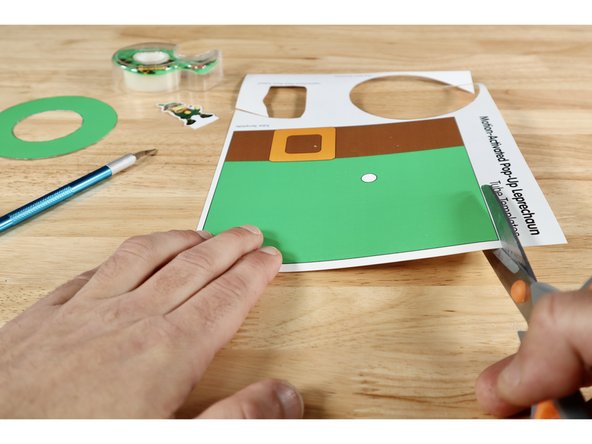
Cut out the two pieces of the tube hat that hides the gear rack. You can also cut out your Leprechaun Topper and the hat brim; setting them aside for later use. The next steps pertain only to the Tube Template.
-
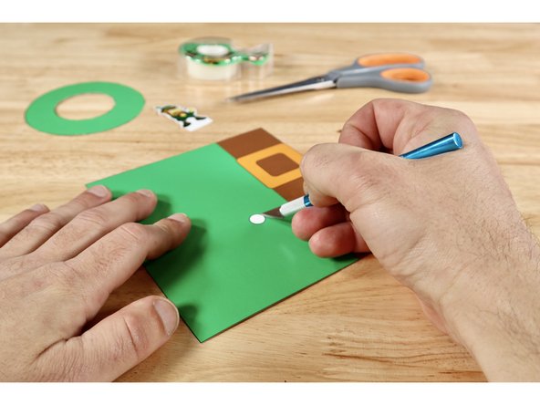
You will need a generous hole through the spot on the tube that is even with the servo axle. This spot is marked on the tube template and it's easier to remove it now before you create the tube shape. Use an Xacto Knife or another tool you favor to cut that small hole out of the tube.
-
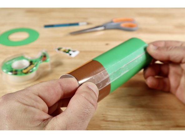
Using the brown belt as a reference for the bottom of the hat piece, curl it into a tube shape and attach at the seam with clear tape. You may benefit from pulling the flat sheet against the edge of a table to begin coaxing it into the tube shape before taping.
-
-
-
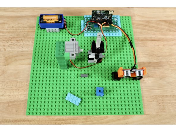
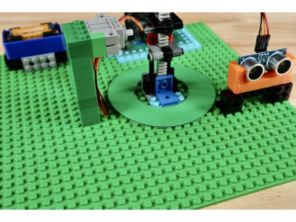
The battery pack, distance sensor, and servo all have cables that will need to connect to pins on the Bit Board. Lay the parts and their mounting builds out first so that they aren't too far for the cables to reach the pin areas on the Bit Board. Leave adequate space immediately adjacent to the servo axle for the gear rack build as well.
-
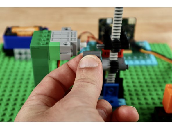
With spacing loosely gauged, press each of the subsystems into place atop the baseplate. Note: There are two unused pieces that are used near the base of the gear rack to firm up its connection and limit the downward travel of the vertically-oriented rack.
-
Pay particular attention to spacing between the servo tower and the gear rack as these two builds need to be close enough for the axle connector to connect the servo axle and the upper axle of the gear rack. The servo tower should be to the left of the gear rack when looking at the teeth.
-
-
-
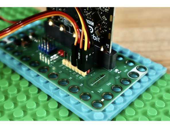
Connect the ribbon cable from the servo to Pin 0 on the Bit Board making sure to orient the plug as shown in slide 1.
-
Use the banded Crazy Circuits ribbon cable to connect the distance sensor to the Bit Board. Slide 2 shows which cables go to which pins on the sensor. Slide 3 shows which cables go to which pins on the Bit Board.
-
-
-
Download the CODE. Connect your Micro: Bit to your computing station and drag the downloaded file onto the Micro:Bit drive icon that should appear when connected to your computer.
-
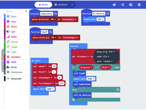
In the "On Start" section, we are setting up some basic understandings for the Micro:Bit to consider so that we can refer to them as named "shorthand" in the rest of the code. We tell it what "Speed" to operate the servo at, what distance indicates the presence of a "Thief", as well as the positions on the servo that mean "UP" and "Down".
-
We also create a few functions to describe to the Micro:Bit what we mean when we tell it "Pop Up" "Go Back Down" or "Do Nothing". Each function includes the PIN number that the servo is plugged into and uses the servo angles we defined in the "On Start" portion of the code.
-
The "Forever Loop" contains a command for the Micro:Bit to constantly compare the values being read by the two parts of the distance sensor and write the result as a new variable called "Distance".
-
There is also a basic "If/Else" statement in that "Forever Loop" with a math comparison between the "Distance" number the sensor is constantly monitoring and the distance you defined in "On Start" as the presence of a "Thief".
-
If the number "Distance" (constantly gathered by the sensor) is shorter than what you defined as the distance for "Thief" the "Pop UP" action is carried out by the servo followed by a 5 second pause and then "Go Back Down".
-
If, at any time the sensor (still constantly reading and producing a value for "Distance") produces a value that is shorter than "Thief", the function called "Pop Up" will be called on again and carried out.
-
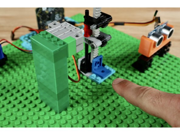
Test the program by placing your hand in front of the sensor. The servo should engage and the gear rack should be driven upward. Take your hand away. There should be a 5 second pause before the servo re-engages and drives the gear back down. Once tested, disconnect the USB cable so the project isn't working while you add decorations.
-
-
-
With all subsystems spaced correctly, connected, and tested it's time to add the final decorations. The hat pieces will all need to be slid down over the gear rack which (for testing purposes) should still be connected to the servo via the axle connector. Remove that axle connector to allow for placement of the leprechaun hat and brim.
-
The brim of the hat does not need to be attached. The center hole is should fit around the gear rack assembly. You need only slide it down and around the gear rack before adding the tube.
-
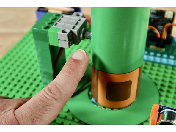
Now do the same with the tube; belt and buckle first. You do not need to attach the brim to the hat tube. Rotate the tube so that the hole you removed for the axle lines up with the axle. Then reattach the servo axle and the axle inside the tube through the hole.
-
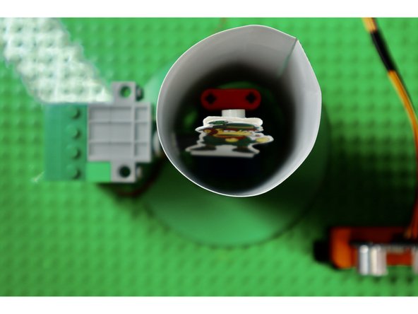
Making sure the long vertical gear is as low as it can go first, use a tape loop to attach your leprechaun guardian to the top of the gear rack. When stuck to the gear at this position, the top of the leprechaun should be even with the top of the hat.
-
-
-
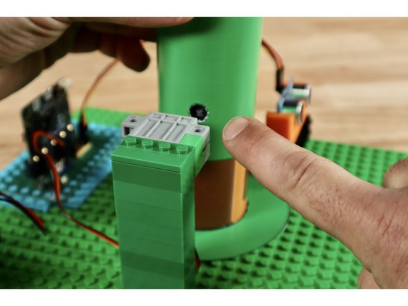
The final connection can be a little tricky to make. Be patient! You will need to connect the servo axle and the axle that is showing through the hole in the hat.
-
Tip: Briefly disconnect the servo tower at its base and add the connector to the servo axle first. Then press the tower back into place and connect to the axle in the hat. You may need to reach a finger into the hat behind the gear rack to support it from behind as you make the final connection.
-
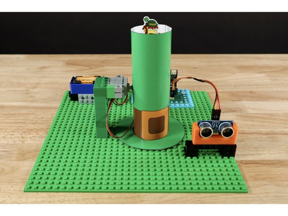
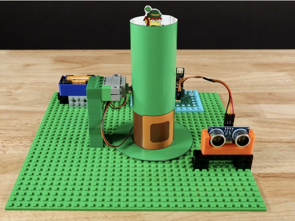
Your project is now complete!
-
When something gets within the prescribed distance of the sensor, the tiny leprechaun pops up, ready to protect what's his!
-
When the object near the sensor "leaves", the leprechaun is programmed to stay on guard for 5 seconds before going back down.
-