Introduction
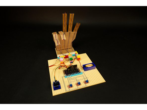
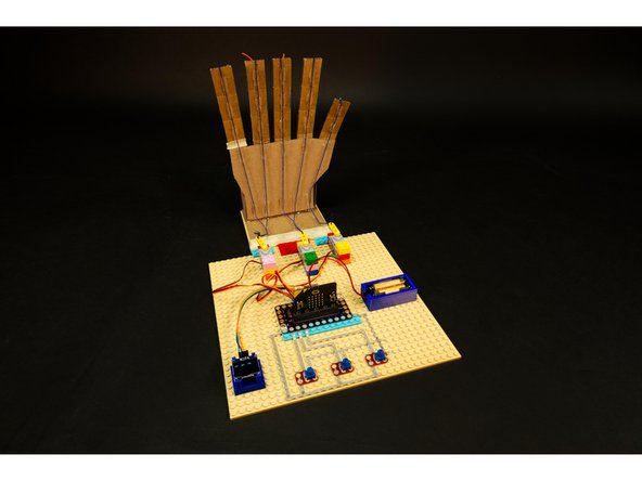
Build a Robotic Hand from cardboard and control it with a micro:bit and our Bit Board.
Video Overview
Featured Document
-
-
Note: We also have a version of this project that uses our Robotics Board: Robotic Hand (Robotics Board)
-
Before we start, let's ask the question "What is Cardboard?"
-
When someone says “cardboard box” you probably think of a brown box that your packages get delivered in. Chances are that “cardboard box” is actually a “corrugated fiberboard carton”.
-
So what is a “cardboard box”? It’s really a chipboard box. The kind that cereal or board games come in. These “cardboard” boxes are not corrugated, and are for lightweight items.
-
Even though we use the term “cardboard box” we’re really referring to a “corrugated fiberboard carton” or “corrugated fiberboard box”.
-
-
-
The corrugation is what gives our cardboard strength, but allows it to still be fairly lightweight.
-
Because we need the fingers of our hand to bend and then flex back in place we need to pay attention to the direction of the flutes.
-
Make sure the corrugation flutes run the long away along the fingers!
-
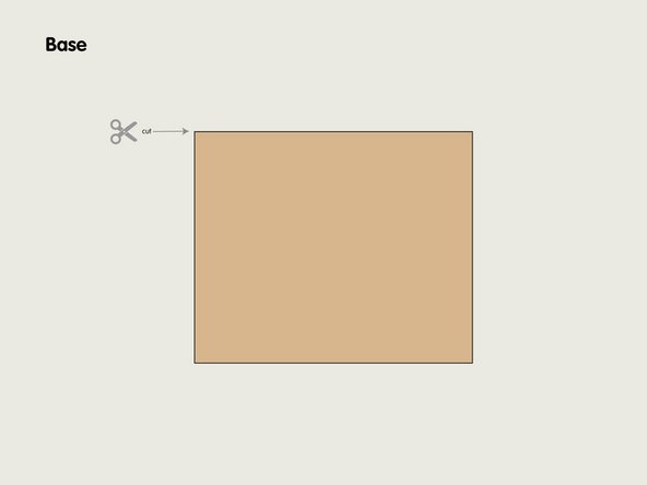
For the hand and the base the flute direction won't matter, but it will for the fingers since they need to bend back and forth.
-
-
-
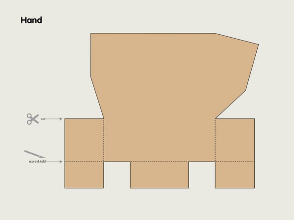
Print out the template and tape (or glue) it to corrugated cardboard.
-
You can cut with a pair of scissors but an X-ACTO knife will give better results.
-
If all you have is a razor knife (box cutter) that can work too, but be careful! Knives are sharp!
-
Can you cut the cardboard with a laser cutter? Sure! Most small laser cutters can cut through cardboard quite easily.
-
Can you scale it up? Sure! Keep in mind how scaling the hand may affect things such as weight and how the other components interact with it.
-
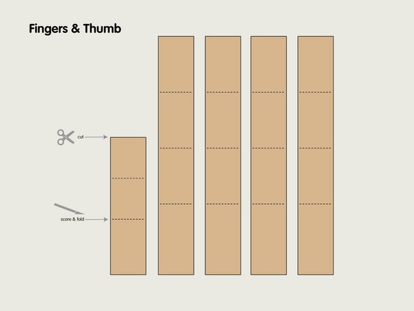
Make note of which lines get cut and which get scored so they can be folded.
-
Scoring will work best with a metal edged ruler and a knife. If you cannot score the cardboard you can just bend & fold it over instead.
-
-
-
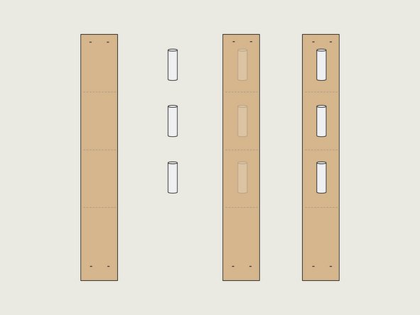
For each finger you’ll need to score and fold in three places, attach three straw pieces with hot glue, and staple a cut rubber band into place.
-
We’ll start with one of the four fingers (they are all the same size) and then you’ll need to do the same with the thumb, though it only has two sections instead of three.
-
-
-
Note: The slits cut into the finger allow it to flex forward. This means the back of the finger is the part with the slits.
-
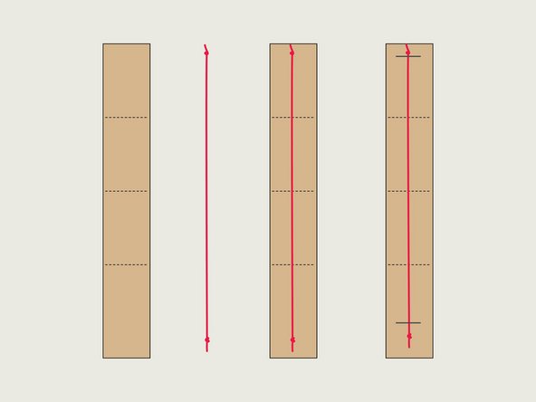
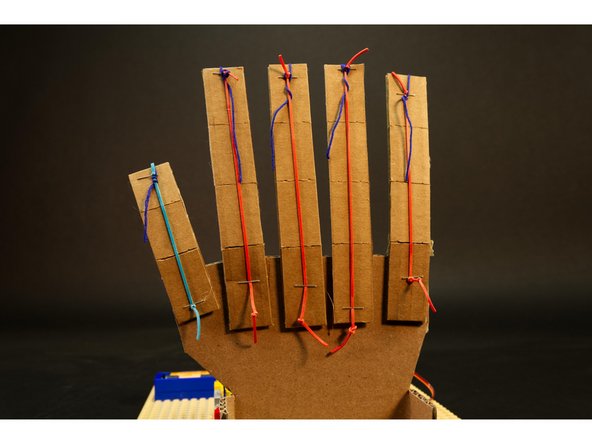
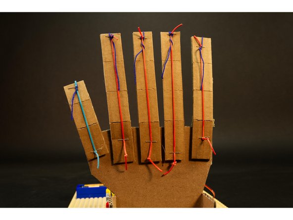
Cut a rubber band so it’s about the length of a finger, and then tie a knot in both ends.
-
Pulling the rubber band just a tiny bit taut, attach the rubber band to the top and bottom of a finger on the back side using a stapler.
-
At the top of the finger the knot should be right up against the staple, and at the bottom it can have a bit of extra slack.
-
You should be able to slide the rubber band beneath the staple to move it into place. (But the knot should keep it from sliding out from under the staple.)
-
The tension can be adjusted by sliding the rubber band at the bottom of the finger beneath the staple.
-
Note: We used thin rubber bands so as to not create too much tension on the finger. We want just enough tension to help the finger return to the upright position, but not too much tension to fight against the servos that will move them.
-
-
-
We used standard clear drinking straws but you can use whatever kind you have available, as long as you can slide the string (or thread) through it.
-
We cut each straw piece to about half the length of a finger segment, and then centered each on a finger segment.
-
When applying hot glue it’s best to lay the finger down flat on a table, put the hot glue onto the cardboard, and then put the straw piece into place.
-
Hot glue can burn fingers! Carefully put the straw pieces in place, trying not to touch the hot glue with your fingers.
-
-
-
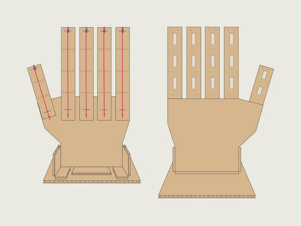
Did you assemble the four fingers and the thumb? If so, you can now attach the fingers to the hand.
-
Note the spacing and position of the fingers in the diagram.
-
You don’t have to match the angle we used (straight up and down) and you can angle your fingers a bit if desired.
-
Once you’ve got the position and angles figured out, use hot glue to stick the fingers onto the back of the hand.
-
Make sure you’ve got your fingers going the correct way! They should flex forward towards the front of the hand! (Straws in front, rubber bands in back.)
-
-
-
With all the fingers in place we are ready to attach the hand so it can stand upright on the base.
-
Fold the scored piece on the bottom of the hand back so you can glue them down to the base.
-
Make sure you mount the hand towards the back of the base, as you'll need room in front of the hand to add the straws and strings.
-
-
-
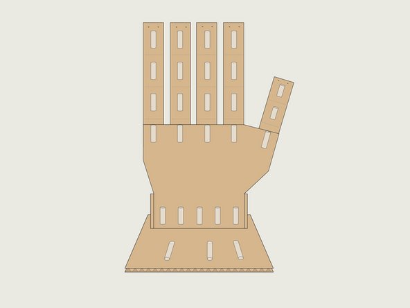
Time to add more straw pieces, so plug in that hot glue gun!
-
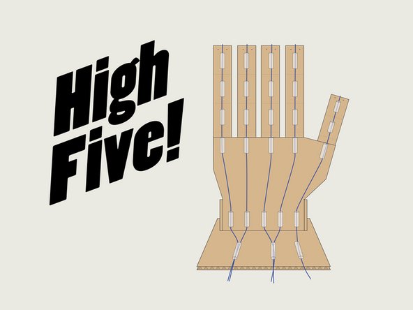
The straws act as a guide for the string we're going to add, so the row right below where the fingers connect should line up with the existing straws on the fingers.
-
For the straws at the bottom of the hand, they should be evenly spaced as shown.
-
Finally, we'll add three more straws on the base that are between the sets of two fingers, and one more for the thumb.
-
-
-
With all the straw pieces in place to guide the strings, it's time to add the strings.
-
Thread the strings through the straws as shown.
-
You'll want a good amount of string sticking out the front set of straws, probably 10 centimeters or so, as you'll need to reach the servos with them.
-
For the string connection to the back of the fingers you can just loop them around the rubber band right behind the staple. They should stay in place just fine. (Wrap around a few times if needed, or add a bit of tape.)
-
Leaving the strings on the back wrapped around the rubber band and not tied means we can easily adjust the tension later if needed.
-
-
-
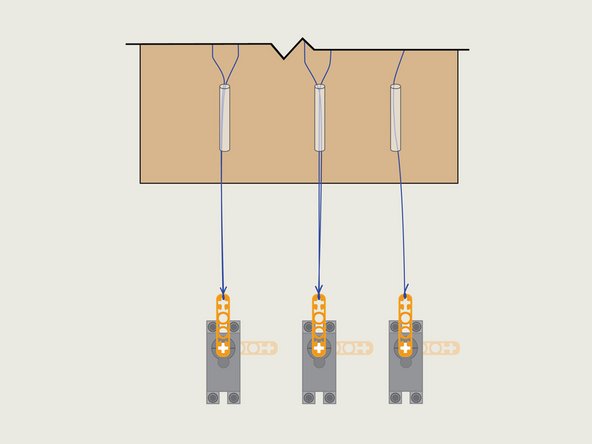
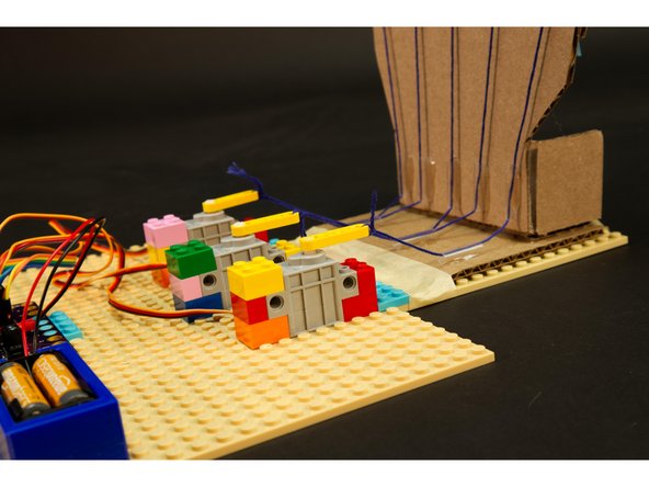
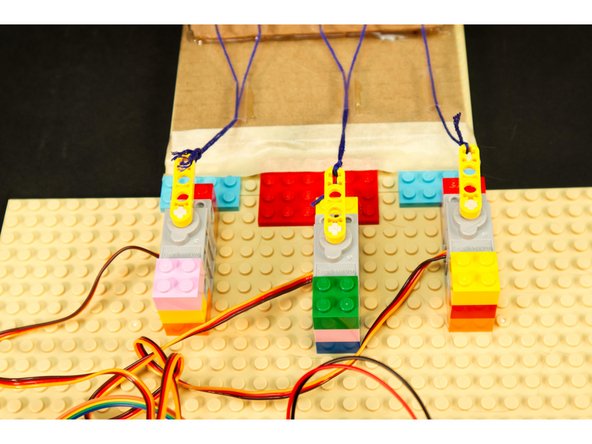
We're going to use three 270 degree LEGO compatible servos with LEGO beams to pull the strings.
-
We attached ours to a LEGO baseplate that we then connected to our cardboard base.
-
The servos should line up closely with the three straws. They don't have to be exact, and you'll need to make sure the LEGO beam can move 90 degrees without hitting anything.
-
-
-
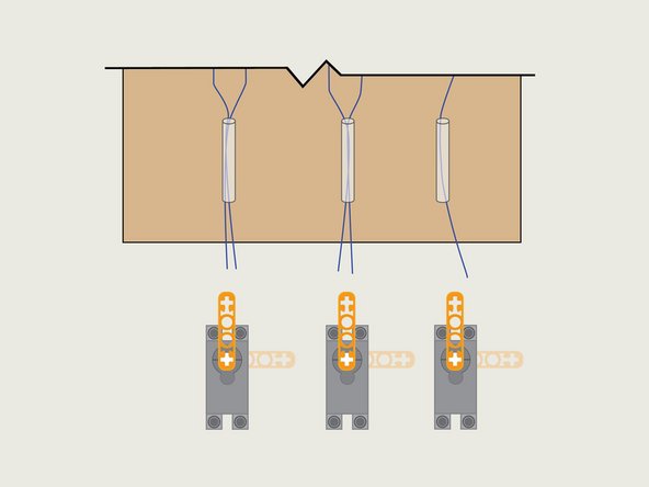
With the servos in place we can now tie the strings onto the LEGO beams.
-
We're going to tie the strings on the servo ends so we can pull them tight at the other end of each string (on the back of the finger).
-
Tie a good knot! You don't want the string to come loose while the hand is in operation.
-
-
-
With the strings tied onto the LEGO beam on each servo you can now pull the strings taut and secure them on the back of each finger.
-
Just wrap the string around the rubber band below the staple.
-
Don't tie the strings! In our testing we found that the strings wrapped around the rubber bands held in place just fine - and also allowed us to adjust tension.
-
You can tie the strings if needed, for instance, if they are slipping, but you may not need to. (Alternately, some tape might work to help hold the strings in place.)
-
-
-
Your Robotic Hand should now be fully assembled!
-
Next we'll be controlling the servos connected to the hand using a micro:bit and our Bit Board. There are a few different ways to do this, so read through the rest of the guide and if you prefer a different method, feel free to do what works for you.
-
New to servos? Check out our intro guide for the LEGO Compatible 270 Degree Servo
-
-
-
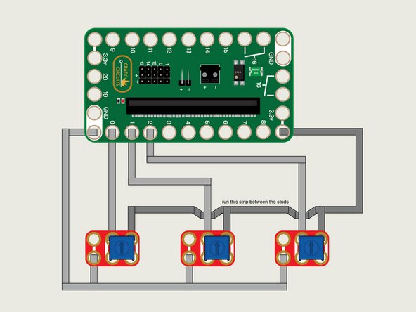
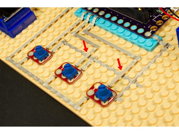
We're going to mount our Crazy Circuits Bit Board and other components to a LEGO baseplate and use Maker Tape to connect three Potentiometer Chips.
-
Each Potentiometer needs to be connected to GND, 3.3V, and an analog input pin.
-
Note that we cannot overlap the Maker Tape from Ground and the Maker Tape from 3.3V because that would cause a short circuit!
-
What we can do is run tape between the LEGO studs, then run tape on top of the LEGO studs so the pieces do not touch.
-
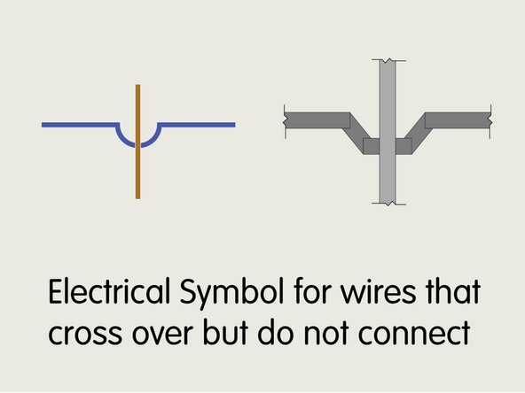
In typical wiring diagrams there’s a special symbol that is used for showing where wires cross over but do not connect. In the diagram we’ve used our own “tape symbol” to show this, but you don’t really need to make this shape with the tape.
-
-
-
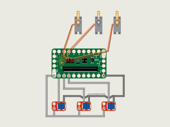
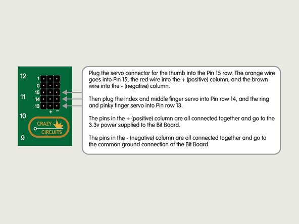
The servos have a three wire connection. The red wire is positive, the brown wire is negative (or ground) and the orange wire is the signal wire.
-
The red and brown wires are used to provide power to the servo, and the orange wire carries the "signal" from the micro:bit that tells the servo what to do.
-
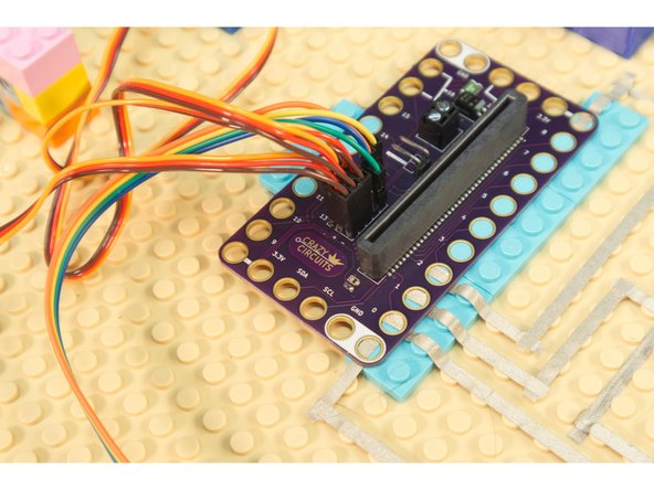
The servos have all three wires together in a connector that plugs right into the pin headers on the Bit Board. Just make sure you plug it in the right way or your servo won't work!
-
-
-
Connect a USB cable to the micro:bit and then plug it into your computer.
-
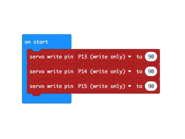
Before we can run our code we'll need to make sure our servos are set to 90 degrees.
-
Create a program that will set the servos to 90 degrees as shown.
-
Before you load this code onto your micro:bit you should remove the LEGO beams on each servo!
-
After you run this code you can place the LEGO beam back onto the servos. We just want to make sure 90 degrees is our starting point.
-
-
-
Connect a USB cable to the micro:bit and then plug it into your computer.
-
We'll be using makecode.microbit.org to program our board. It uses a simple drag and drop block interface.
-
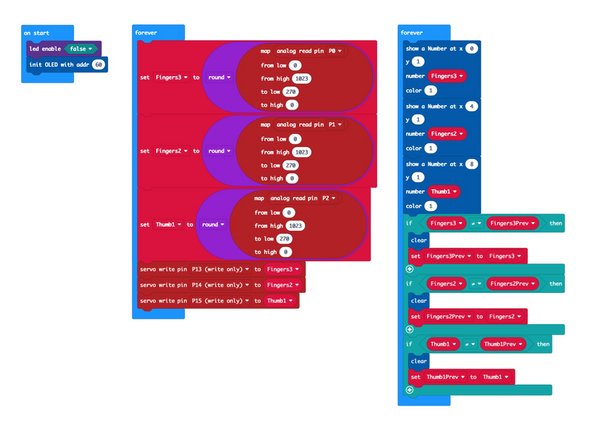
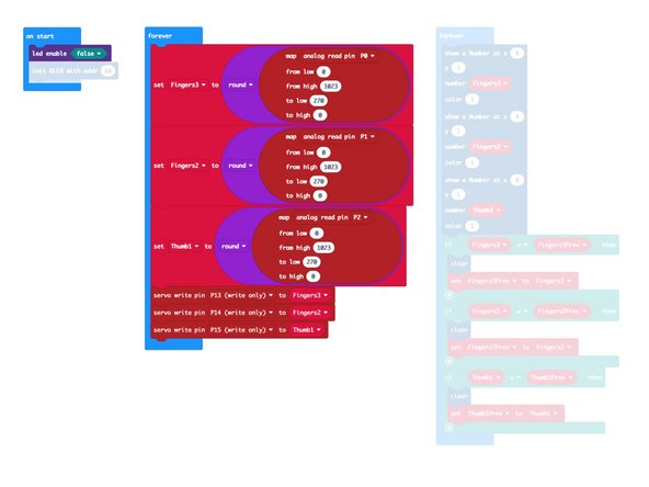
We're going to load the following code for our Robotic Hand program: https://makecode.microbit.org/_2f4CW6MJR...
-
Note: Our code has an extra block in the on start section and an extra forever section to control an OLED Display but if you are not using one you can ignore those parts of the code.
-
-
-
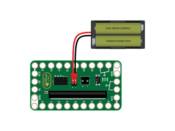
We're almost ready to try it out! Since this project uses multiple servos you'll need to plug in a battery pack to provide 3 volts to the Bit Board, which will provide the power needed to get our servos moving.
-
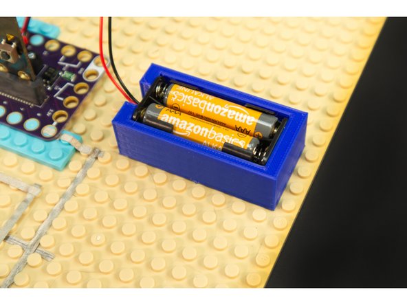
If you've got a 3D printer around, you can print our 2AAA Battery Holder.
-
-
-
We're ready to test out our Robotic Hand!
-
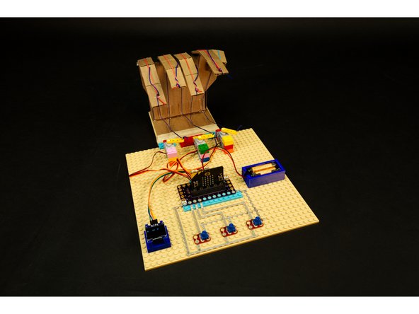
As you turn the potentiometers the fingers should start to close. If you turn the potentiometers back the fingers should return to an extended position.
-
If you need to adjust the tension you can pull the rubber bands tight at the bottom of the fingers.
-
If you need to adjust the strings you can change the tension where the string wraps around the rubber band at the top of the fingers.
-
If your finger joints are too loose and flop down you can add a piece of masking tape or painter's tape to the joint on the front of the finger to add some stiffness.
-
-
-
Congrats! You just built a cardboard hand and controlled it with a micro:bit!
-
-
-
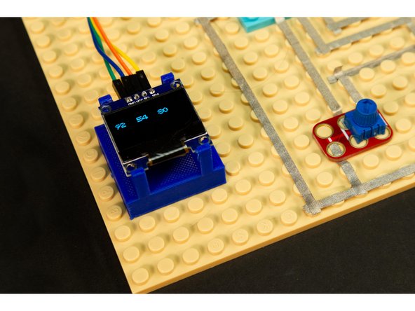
This step is optional, but the code will support the addition of an OLED Display to show the angles of the three servos.
-
The OLED Display we used is an I2C device, and needs to connect to specific pins on the Bit Board. See this guide for more info: OLED Display
-
If you want to easily mount the OLED Display, and you have access to a 3D printer, check out our file: OLED Display Holder
-
Cancel: I did not complete this guide.
One other person completed this guide.


