
Introduction
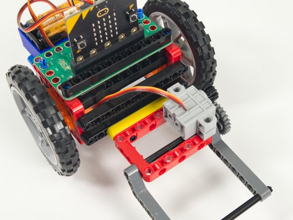
If you've built our Rover Main Body this is a great accessory. An easy-to-build Lifter than can attach to the front of the Rover.
Video Overview
Featured Document
-
-
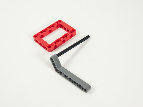
Gather the parts needed to assemble the Lifter.
-
You'll need the parts shown along with a Brick Compatible 270 Degree Servo.
-
-
-
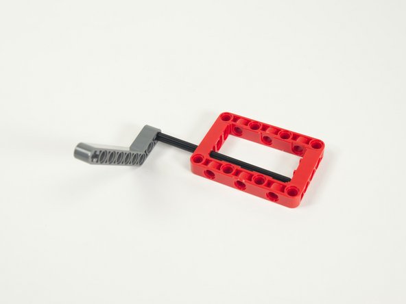
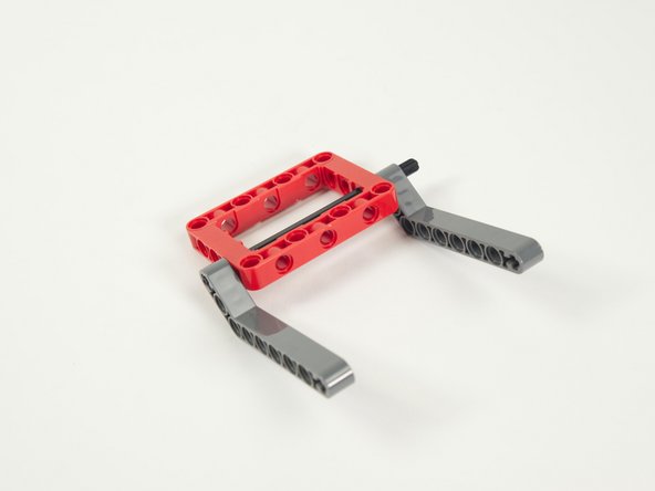
We'll start by sliding the gray axle into the gray angled beam.
-
The axle should be flush with the end of the beam.
-
-
-
Slide the axle (with the beam attached) into the red frame.
-
-
-
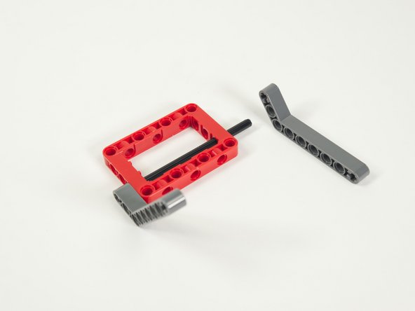
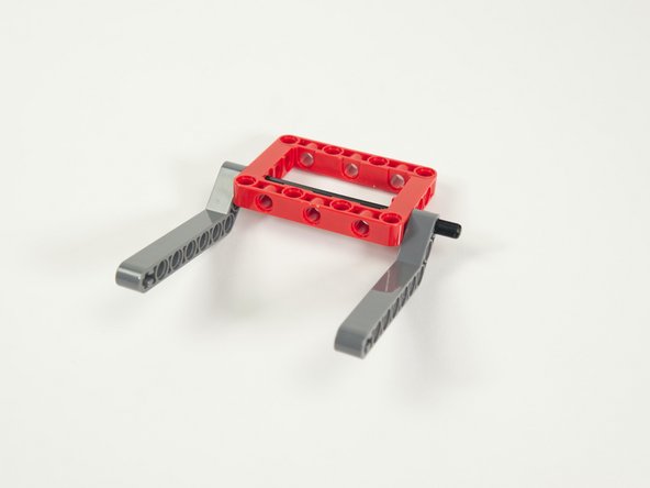
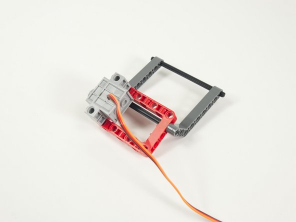
Add the second angled beam to the other side.
-
Note that the axle should stick out from the second beam, as this is where we'll add the large gear in Step 9.
-
-
-
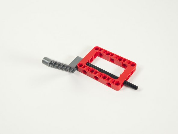
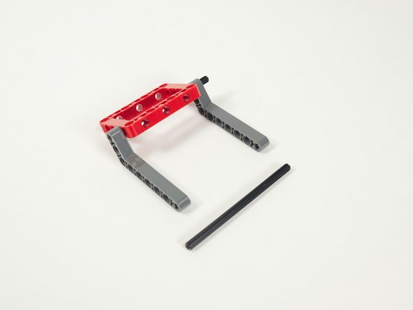
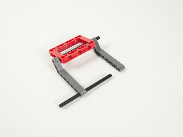
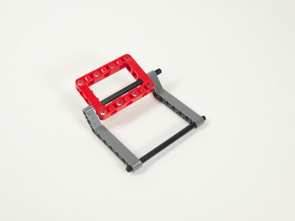
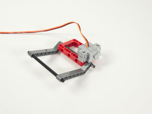
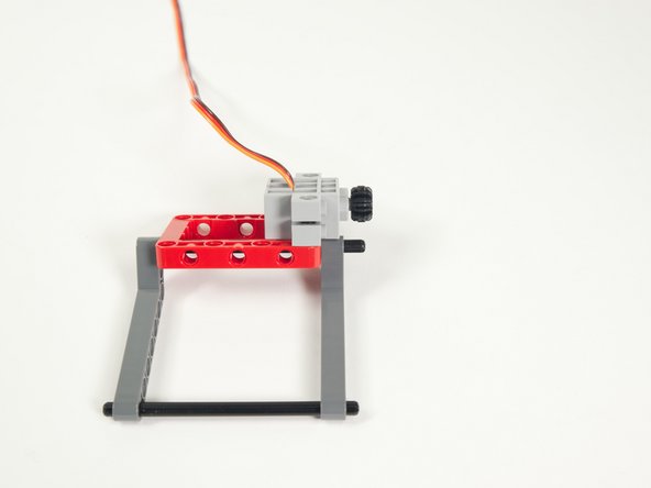
Add the other axle by sliding it into the first holes in the angled beams.
-
Try to center the axle and make sure the beams are not angled in or out - they should be facing straight out.
-
-
-
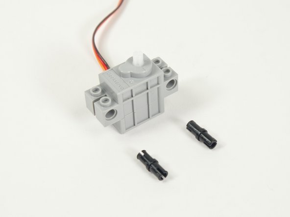
Now let's prepare our servo.
-
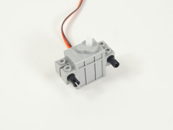
Add two black pins to the servo.
-
Make sure you add the pins to the side of the servo opposite where the wires are connected.
-
-
-
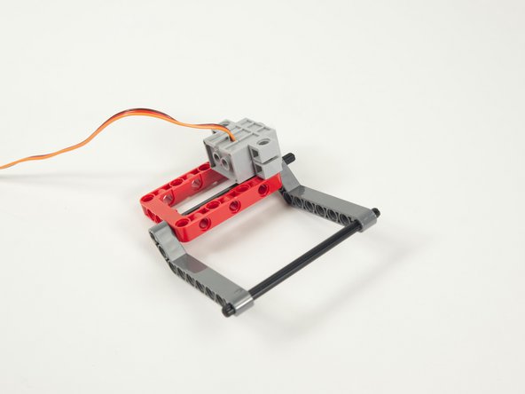
Attach the servo to the frame using the black pins we just added.
-
Note that the shaft of the servo is towards the back of the Lifter and the wires are on top of the servo.
-
-
-
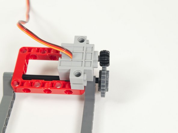
Next we'll press the small gray gear onto the servo shaft.
-
Make sure to press the gear all the way onto the shaft. This ensures it lines up with the other gear we'll add next.
-
-
-
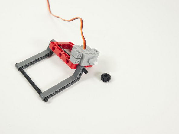
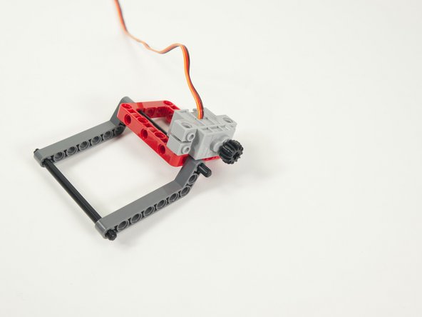
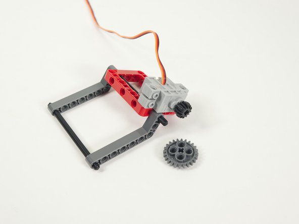
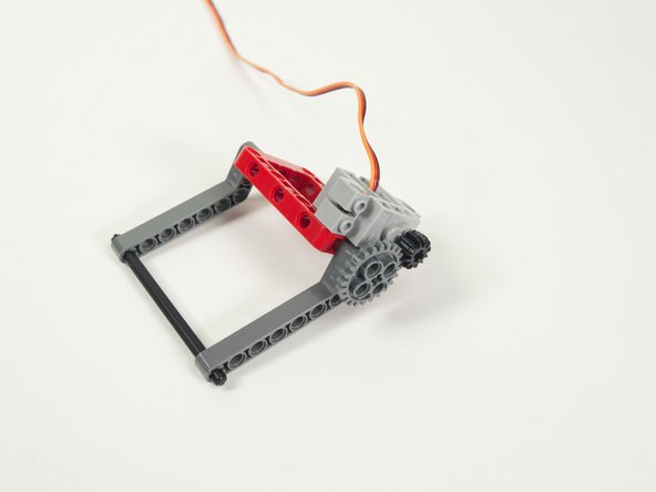
Add the large gray gear to the portion of the axle that is sticking out.
-
Make sure the gear is lined up and centered with the smaller gear that is on the servo.
-
-
-
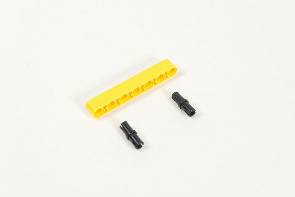
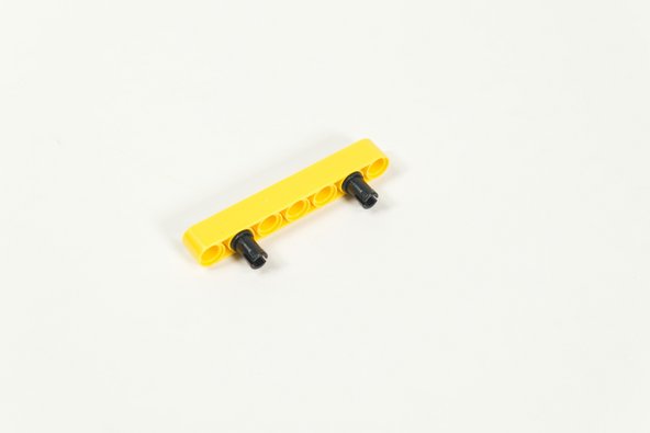
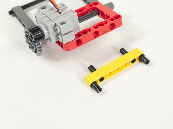
Add two black pins to the yellow 7 hole beam.
-
Place them into the second hole on each end.
-
-
-
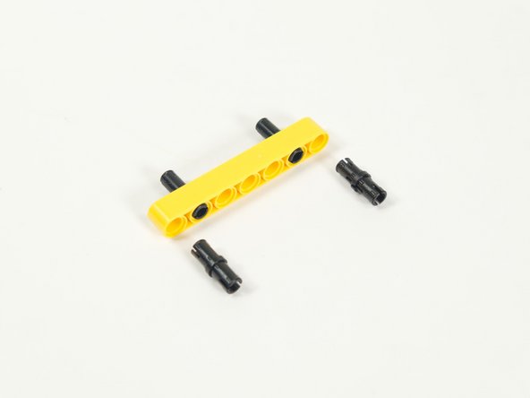
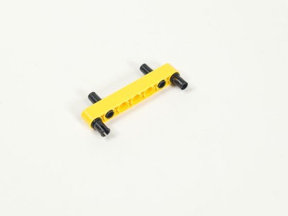
Add two more black pins on the opposite side.
-
These should go in the holes closest to the end of the beam.
-
-
-
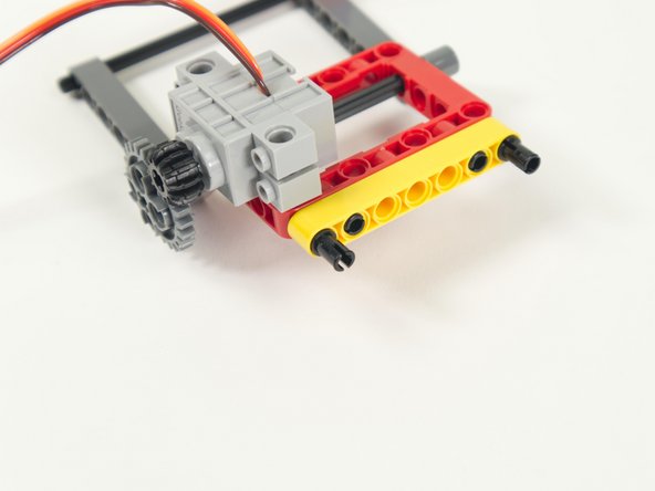
Add the beam to the back of the Lifter's frame.
-
Connect the side that lines up with the holes in the frame.
-
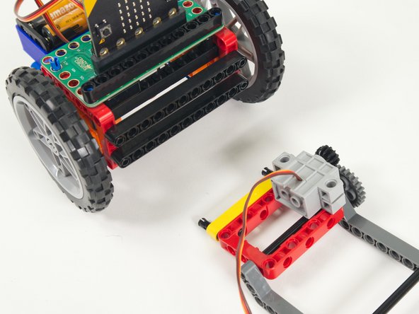
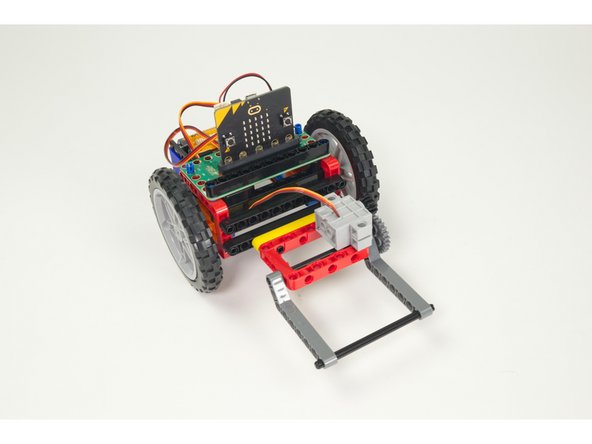
We're now ready to attach the Lifter to the Rover!
-
-
-
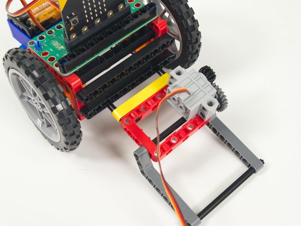
Attach the Lifter to the lower beam on the front of the Rover.
-
Center it and push it in so the pins lock it in place.
-
-
-
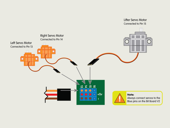
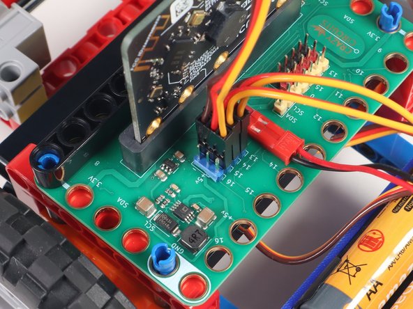
Plug the servo connector into the row for Pin 15. The orange wire should go to the pin closest to the 15 on the board, the red wire goes into the +5v row, and the brown wire goes into the - row, which is ground.
-
All servos should go to the 5V Blue Pins.
-
-
-
If you've never used a micro:bit before you'll want to check out this guide: Bit Board V2 Setup and Use
-
We're going to load the following code for our Lifter Test Code program: https://makecode.microbit.org/_5kc9Yx7W2...
-
This code is very simple, and is just meant to test the Lifter.
-
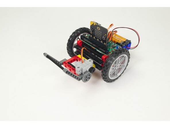
When you press the A button on the front of the micro:bit it should raise the Lifter.
-
When you press the B button on the front of the micro:bit it should lower the Lifter.
-
-
-
To test the Lifter power the Bit Board with the battery pack.
-
If the angles are not correct you can change the values in the code, but you can also remove the large gear, swing the beams to the correct position, and the reattach the gear.
-
Between moving the large gear, and changing the values in the code, you should be able to get the lifter to the exact angles you want.
-
-
-
If you've got a Rover Thumbstick Remote you can use the following code to control the Rover and Lifter.
-
Load the Rover code for the Thumb Remote Lifter TX onto the micro:bit on the Remote: https://makecode.microbit.org/_g6yVVV489...
-
And load the Rover Thumb Remote Lifter RX onto the micro:bit on the Rover: https://makecode.microbit.org/_RCdey2K72...
-
Once the code is loaded you can drive around your Rover and lift things!
-
-
-
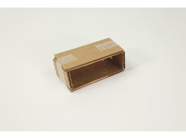
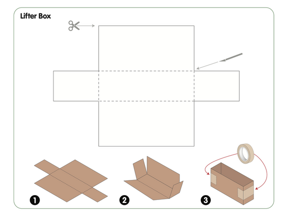
We've included a PDF template with this guide that you can download and print, and then use to cut out and assemble a small box that is perfect for lifting.
-
We recommend cardboard, but you could also make the box using card stock or just plain paper.
-
We've designed the box the right size to work with the Lifter, but you can try other sizes as a problem-solving exercise.
-
-
-
If you've got the Remote code working with the Rover you can drive the Rover and Lift things... Give it a try!
-
-
-
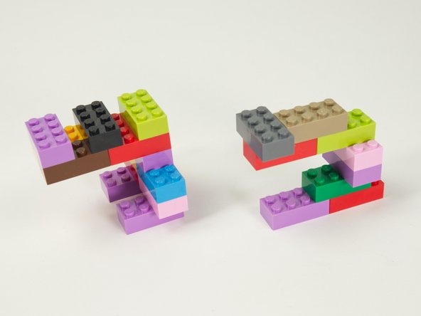
You can build other objects to lift. Here are some LEGO bricks we used to build some objects.
-
Note that you need to design and build an object that is capable of being lifted, which can be a challenge!
-
In fact, you can turn the task of building a liftable object into a good design challenge.
-
-
-
Our simple brick-based object can be lifted, but special consideration needs to be applied to create a liftable object.
-
-
-
The Rover Lifter is quite different than the Rover Gripper so it creates an entirely new set of challenges and activities.
-
We'll be creating more guides for both of them, and welcome any feedback about how you are using the Rover and accessories!
-


Attached Documents
