Introduction
Let's build a Tank! This project uses a set of LEGO Technic components along with our Bit Board, a micro:bit, and two servos to build and program a small tank.
Once you have your Tank built other guides will show you how to extend the programming and add accessories and capabilities to the Tank.
This is a companion guide to our Rover Main Body.
Video Overview
-
-
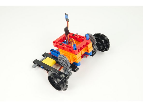
Gather the parts needed to assemble the tank.
-
Besides the beams, pins, frames, and other pieces there are four sprockets, 42 tank treads, and one 3D printed part.
-
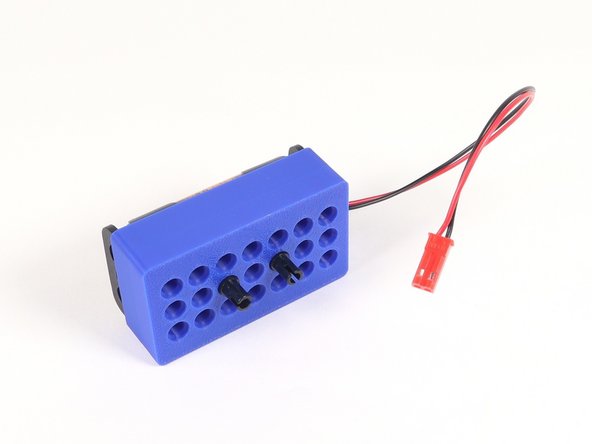
The battery pack holder is a Technic-compatible 3D printed part that we'll use to hold the tank's battery pack. This is most likely already assembled with the battery pack in place.
-
-
-
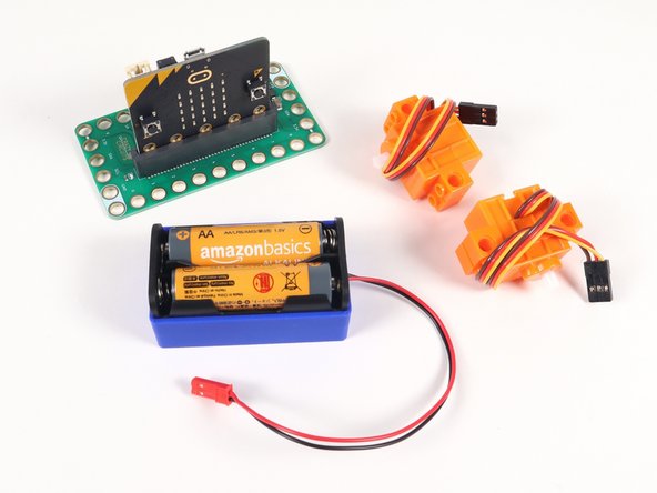
You'll also need a Bit Board and micro:bit, along with two Brick Compatible Continuous Rotation 360 Degree Servos, and a Battery Pack.
-
-
-
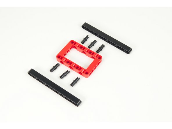
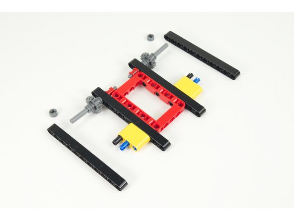
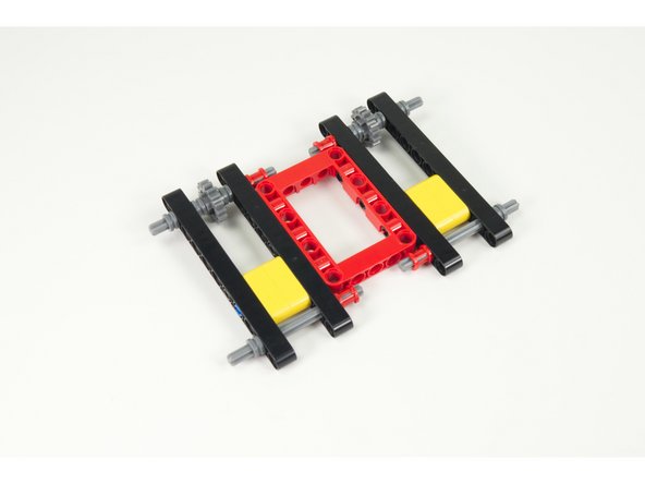
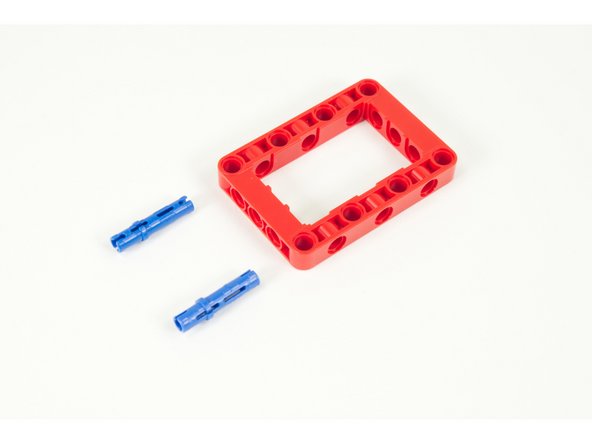
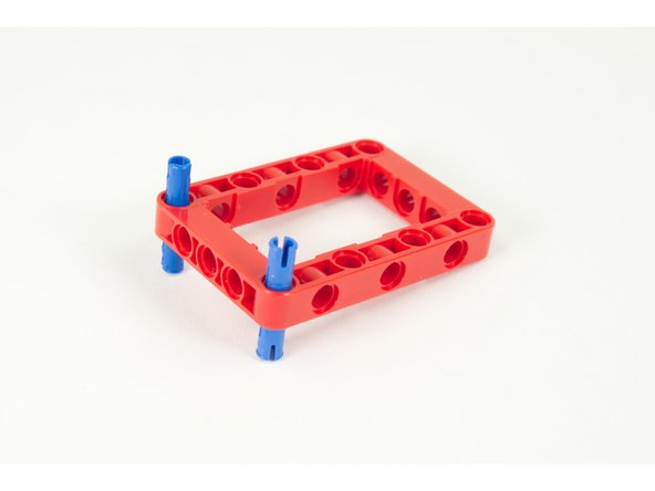
We'll start with one of the frame pieces, 6 pins, and two long 11 hole beams.
-
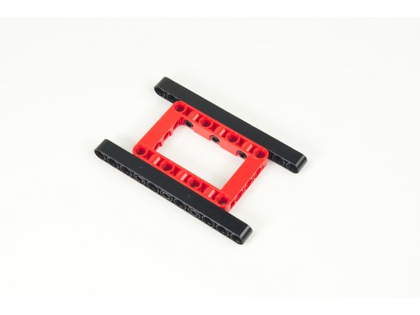
Assemble the parts as shown.
-
-
-
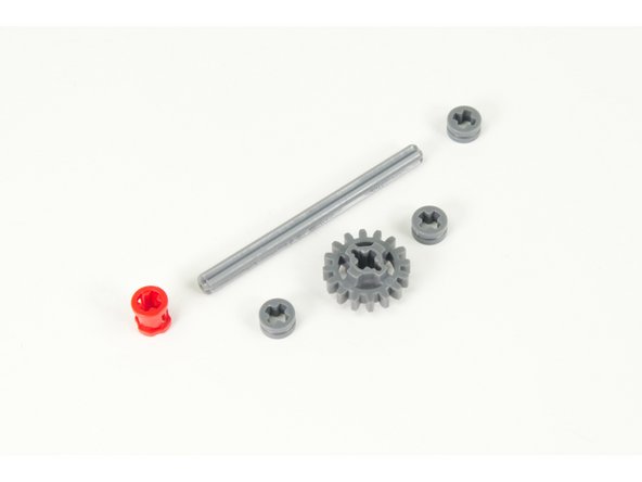
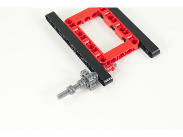
Prepare the front axle assembly. We'll be making two of these.
-
For each one you will need one axle, three half-size bushings, one full-size bushing, and the small gear.
-
-
-
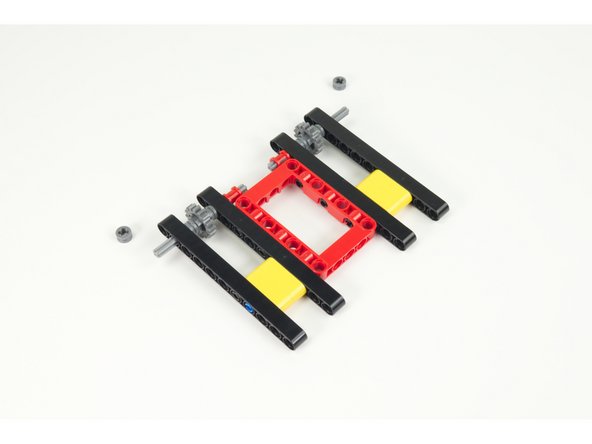
Slide the axle into the second hole of the 11 hole beam.
-
Place the large bushing on the end, inside the frame.
-
Add a half-size bushing, then the gear, then another half-size bushing. Press them all together tight.
-
Add the final bushing, placed about half way down the exposed part of the axle.
-
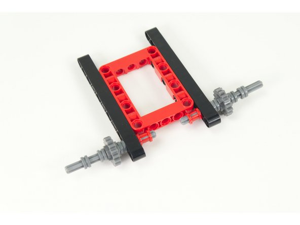
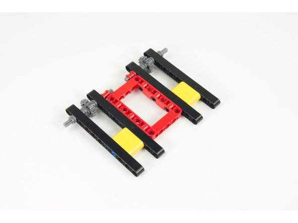
Once you've completed one side, do the other side the same way.
-
-
-
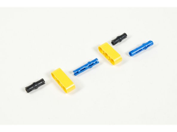
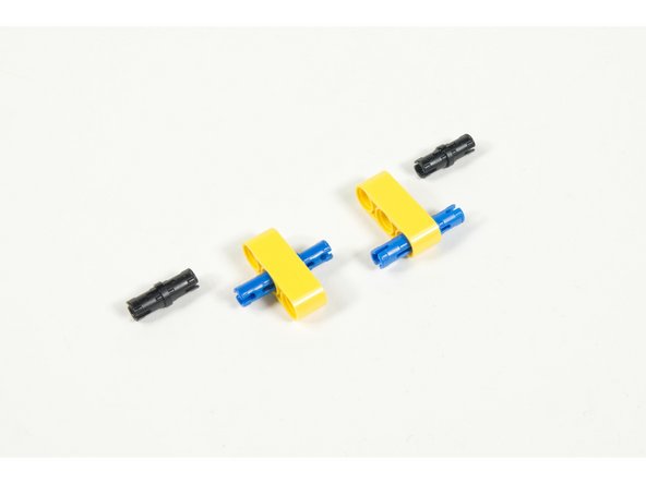
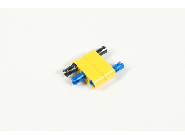
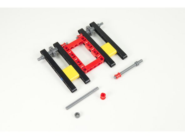
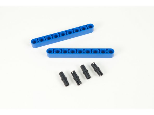
To connect the larger beams we'll build a small connector using two 3 hole beams, two long (blue) pins, and two regular (black) pins.
-
Assemble as shown. The long pins connect the two beams together.
-
After you make one of these connectors, make another one.
-
-
-
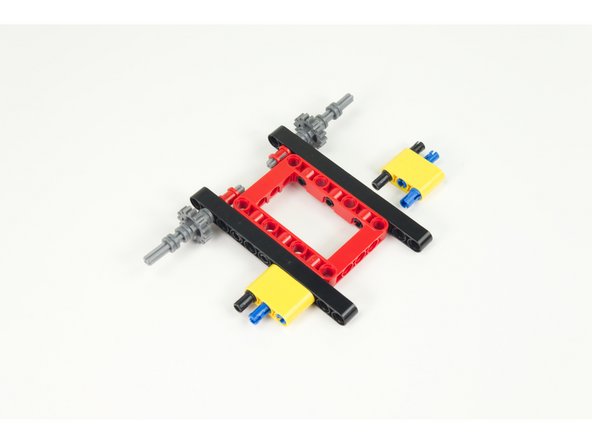
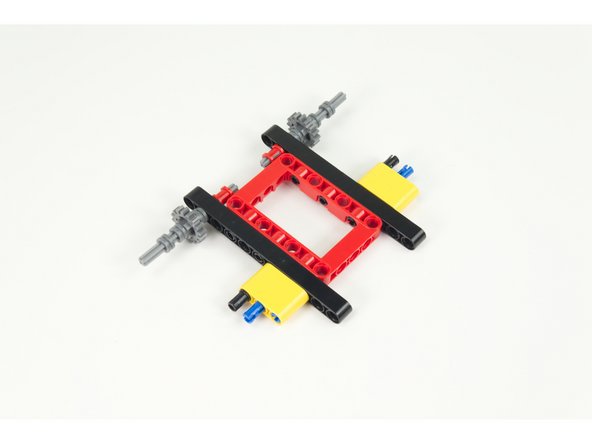
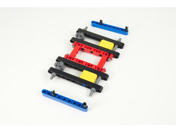
Add the connectors to the main frame of the tank.
-
Note the orientation of the connectors in the photo. Make sure you leave two holes accessible at the end of the beam.
-
-
-
We'll need to temporarily remove the half-size bushing we added in Step 5 so we can add the outside beams.
-
-
-
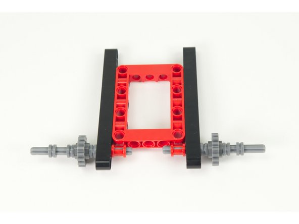
Add the outside beams as shown, then put the half-size bushing back in place on the front axles.
-
The bushing should fit tight against the outside beams we just added.
-
-
-
Next we'll add the rear axles. Get two more axles, two more half-size bushings, and two more full size bushings.
-
Assemble as shown.
-
Press the half-size bushing tight against the outer beams.
-
-
-
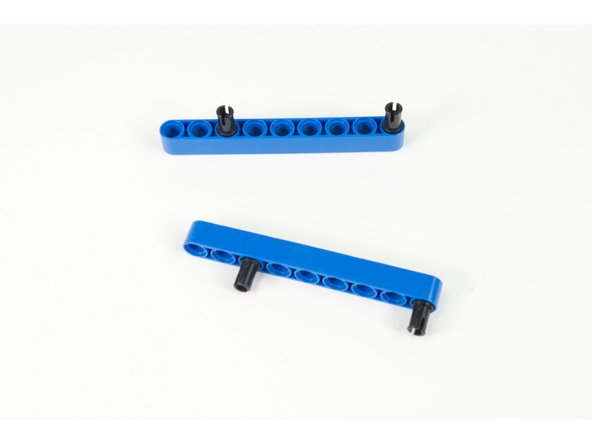
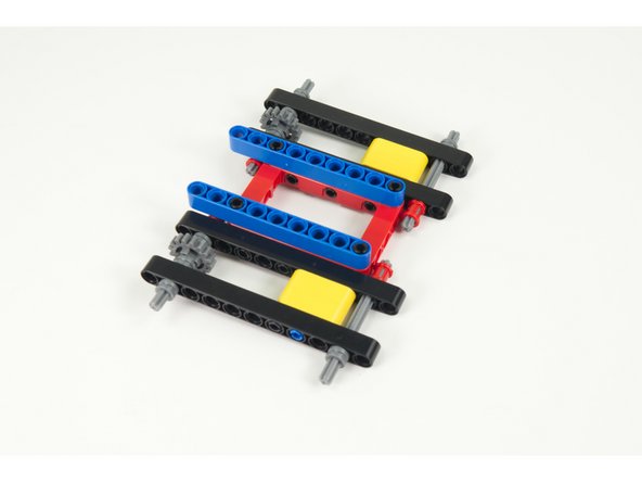
We'll use two 9 hole beams and four pins to raise up our servos to the correct height on the frame.
-
Assembled pins and beams as shown. One pin should go in the third hole at one end, and the last hole at the other end.
-
-
-
Add the beams to the frame, lining up with the front of the frame.
-
The pin in the third hole should be towards the front of the tank, and the pin in the last hole should be near the rear.
-
-
-
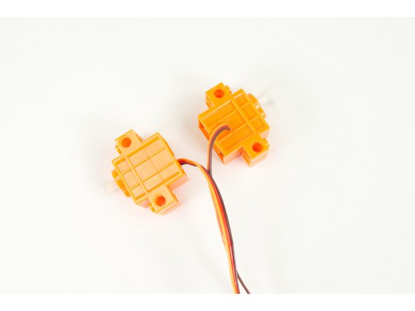
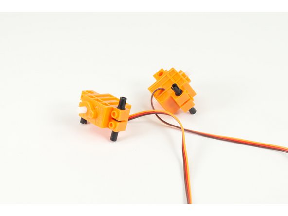
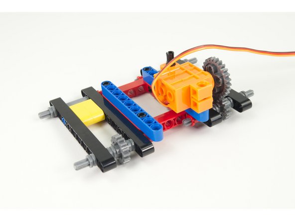
It's servo time! Make note of the orientation of the servos. We need the shafts to line up so one of the servos will be mirrored.
-
Notice the servo on the left has the wires coming up from the bottom side, while the servo on the right has the wires on the top side of the servo.
-
-
-
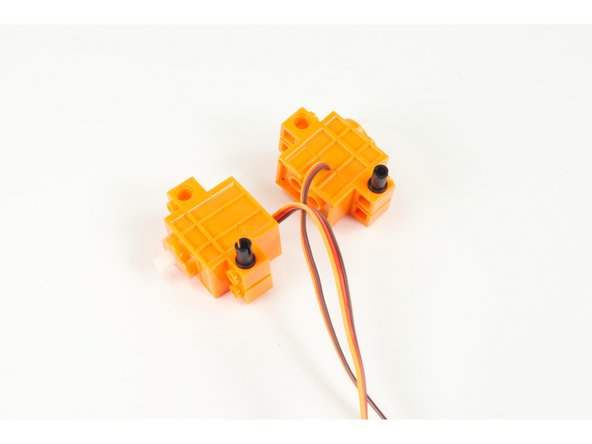
We'll start by adding one pin to each servo on the "top" side.
-
Then turn each servo over and add two pins to the bottom.
-
Once done adding all pins flip the servos over again so they are right-side up.
-
-
-
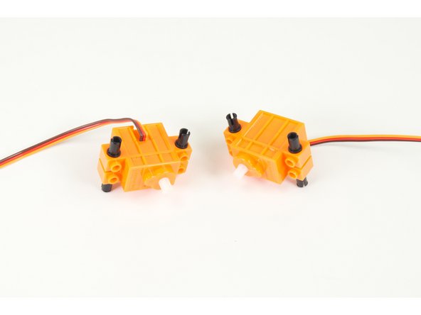
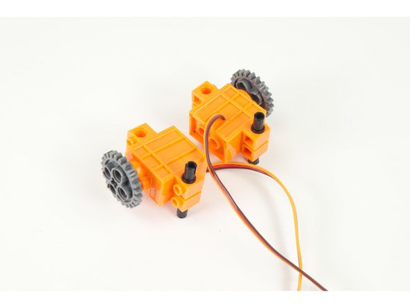
Add the large gears to the servo shafts.
-
-
-
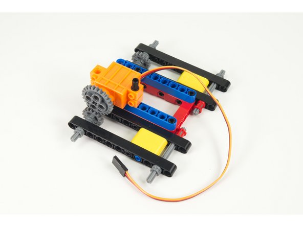
Add the left servo to the frame.
-
Note: When we say "left" we assume we are standing behind the tank, facing the same direction.
-
Note how the gear of the servo lines up with the gear on the axle. If it's a little bit off just slide the gear a bit on the servo shaft. (It doesn't have to be perfect!)
-
-
-
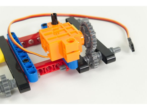
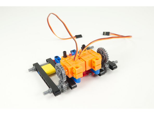
Add the second (right side) servo to the frame.
-
Make sure both servos are pressed into place properly so the gears mesh together with the axle gears.
-
-
-
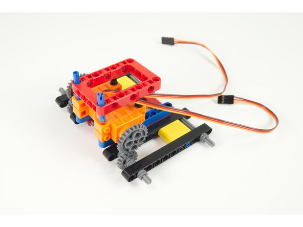
With our servos in place we're going to add the second frame on top of them.
-
You'll need the frame along with two long pins.
-
Place the pins into the frame as shown, so they stick out equally above and below the frame.
-
-
-
Press the top frame in place so the longer pins go into the holes on the front of the servos and the pins already in the back half of the servos go into the holes at the back of the frame.
-
If the wires for the servos are in the way, don't worry... We'll deal with those next!
-
-
-
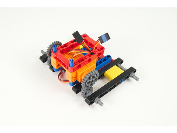
Just a note on cable management. You'll notice a few things...
-
We added a piece of blue tape to the left servo connector. This is to help us identify which servo plugs into which pins later on.
-
We've routed the extra length of servo wire down below the top frame, but put the connectors up through the inside of the frame.
-
We want to make sure the extra servo wires do not get tangled in the tank treads while in motion.
-
-
-
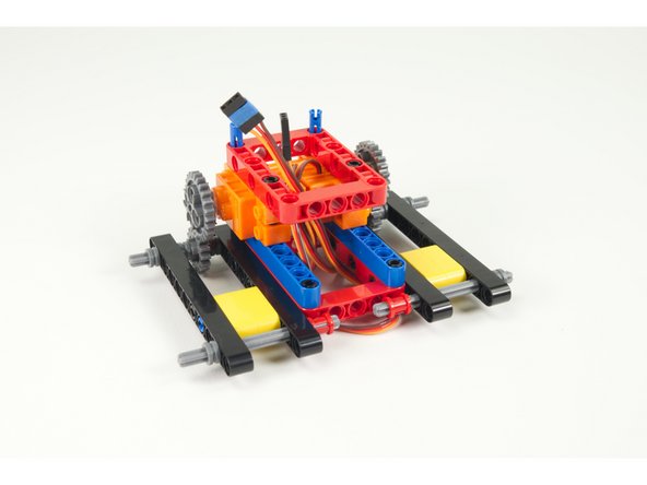
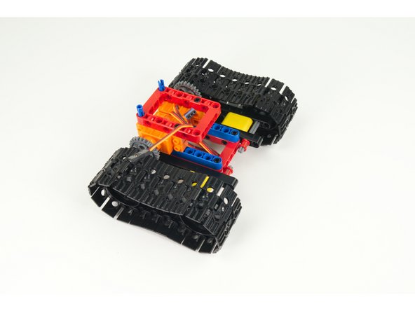
We can now slide the two front sprockets onto the two front axles.
-
Remember, there should be a half-size bushing already on the axle that the sprocket will slide up against.
-
The sprockets are symmetrical so orientation should not matter.
-
Make sure the sprockets are pressed up against the half-size bushing. The bushing is there to properly space the sprocket from the outside beam.
-
-
-
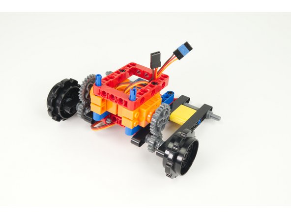
Add the rear sprockets just like you added the front ones.
-
Again, make sure the half-size bushing is in place, and press the sprocket up against it.
-
Once you've got all the sprockets in place we can keep moving!
-
-
-
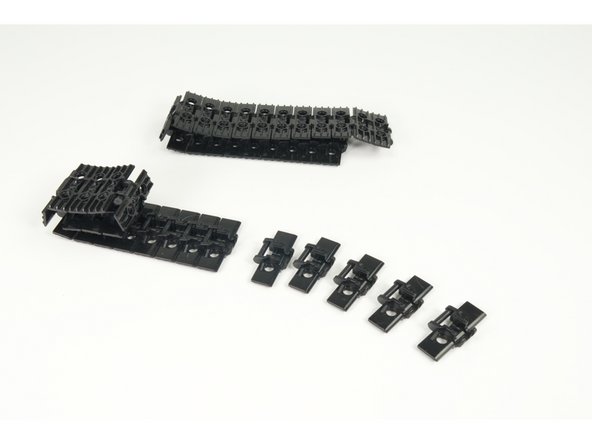
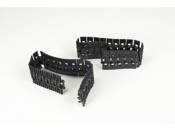
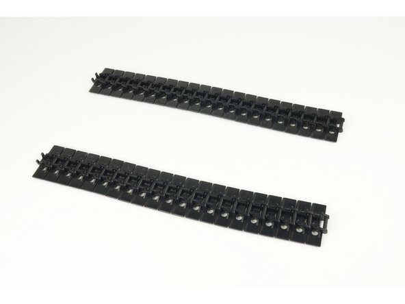
Snap together the track pieces to make two lengths of track, each containing 21 pieces.
-
Once you have your two tracks assembled, place them parallel to each other for wrapping around the sprockets.
-
Note! If you have to use 22 pieces instead of 21 it just means you placed the axle one hole forward in Step 5.
-
-
-
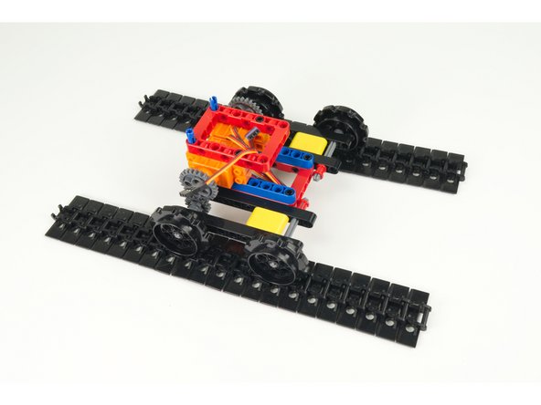
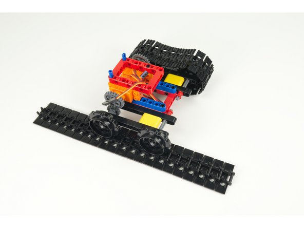
Place the Tank onto the tank treads with the sprockets centered on the tracks.
-
Snap the ends of the tracks together on each side.
-
With the tracks in place it's starting to look like a tank!
-
-
-
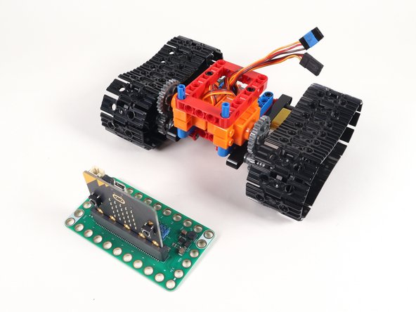
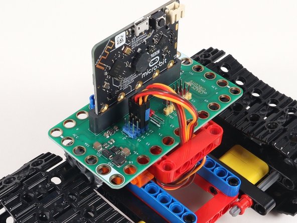
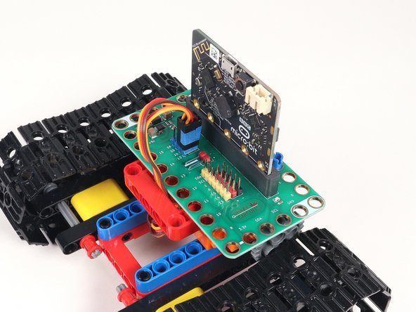
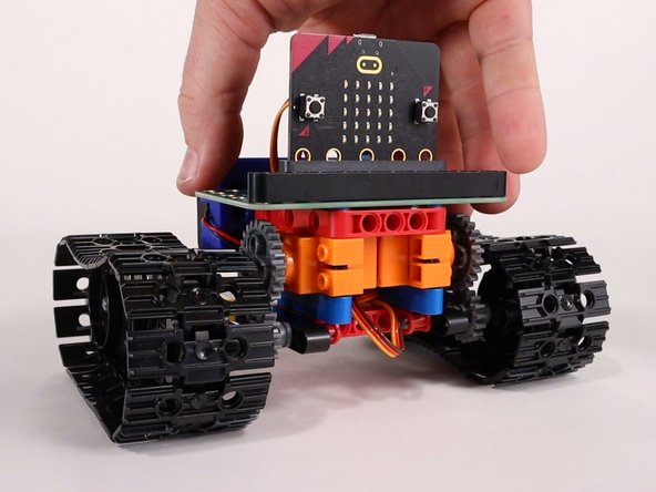
The Bit Board fits onto the two long pins sticking out of the top of the frame.
-
Make sure the micro:bit is facing the right way when inserted into the Bit Board!
-
-
-
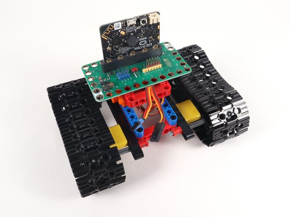
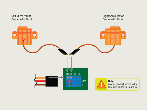
Plug the left servo connector into the row for Pin 13. The orange wire should go to the pin closest to the 13 on the board, the red wire goes into the +5v row, and the brown wire goes into the - row, which is ground.
-
Remember when we added a piece of tape to the left servo in Step 20? This is where it comes in handy!
-
Plug the right servo into the row for Pin 14, matching the orientation of the servo connector for the left servo.
-
Make note of Pin 15. We're not connecting anything to it now, but other guides will use Pin 15 to connect a third servo for additional accessories.
-
-
-
You'll need two pins to attach the battery holder.
-
Place the pins spaced as shown, centered, with one hole open between them.
-
The battery holder is a 3D printed part that is LEGO Technic compatible.
-
-
-
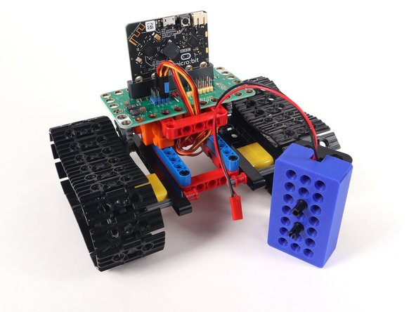
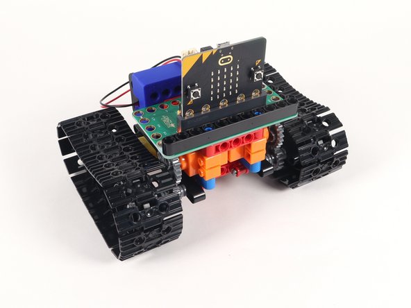
The battery holder will attach to the top frame piece sideways, as shown.
-
You should make sure the wires of the battery pack do not interfere with the tank treads.
-
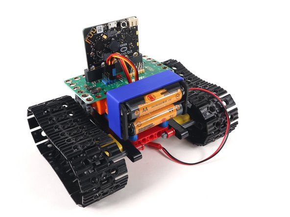
Since the battery pack has a variety of holes to choose from you can also opt to connect it in other orientations.
-
-
-
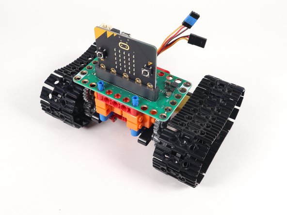
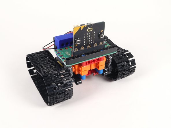
Add a long black beam onto the blue pins to help secure the Bit Board down.
-
-
-
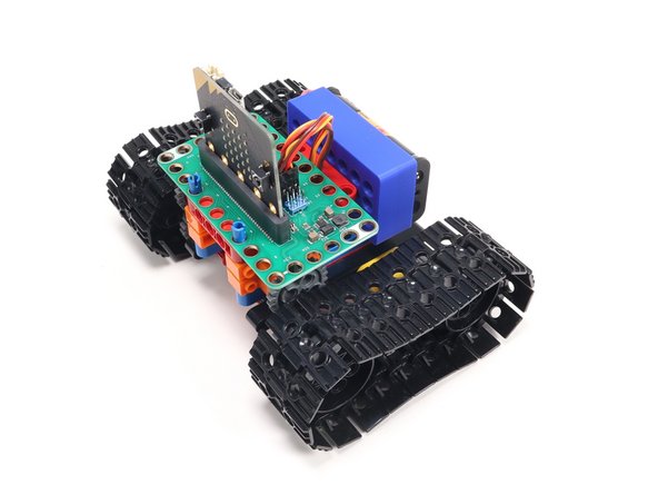
You've just built the Tank! Take a second to admire your work.
-
The great thing about this tank is that it's easy to modify it, to add or remove parts, and experiment.
-
We've added another guide for a Rover Gripper you can attach and control, as well as a Rover Lifter, and a Rover Sweeper.
-
We've got a distance sensor we can add to the front to make the tank avoid running into things.
-
But first... Let's add some code so the tank can move.
-
-
-
If you've never used a micro:bit before you'll want to check out this guide: Bit Board V2 Setup and Use
-
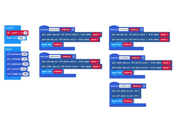
We're going to load the following code for our Tank Test Code program: https://makecode.microbit.org/_iwzi617vx...
-
This test code is very simple. Be aware that your tank will start moving three seconds after the code is loaded, so be ready for that!
-
If you want to change that just edit the pause block in the on start section. (Note: 3000 milliseconds equals 3 seconds.)
-
Another trick is to just remove the micro:bit from the Bit Board when you upload the code and then insert it back into the Bit Board when you're ready to go.
-
-
-
With the code uploaded you should be ready to test it out!
-
Use a large flat surface. The floor will work well, or a table - just be ready to catch the tank if it gets too close to the edge!
-
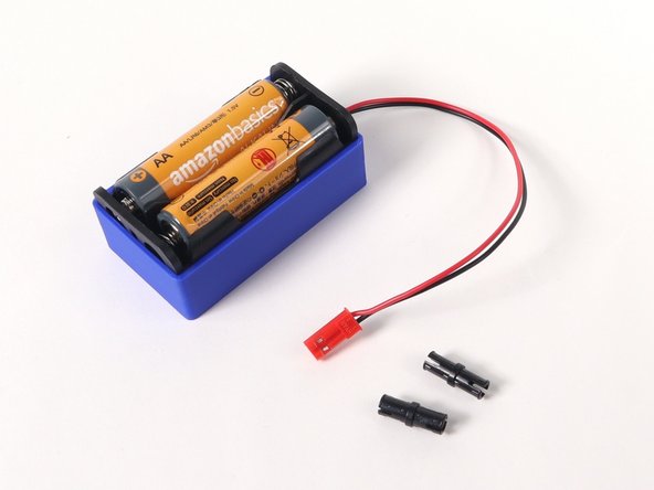
Plug the battery into the Bit Board, wait three seconds, and your tank should move.
-
If your tank moved properly (forward, turn right, backward, turn left, stop) then all is well and you're ready to extend your Tank by adding accessories, remote control, and other capabilities.
-