
Introduction
This guide will help you get started with using the Bit Board V2 with a micro:bit
Brand new to the micro:bit? Check out the official set-up guide https://microbit.org/get-started/first-s...
Microsoft’s MakeCode editor is the perfect way to start programming and get creating with the BBC micro:bit. Learn more at https://microbit.org/code/
Video Overview
-
-
We recommend starting by watching the Bit Board V2 Setup and Use video above. It will cover how to load code onto the micro:bit as well as the basics of the Crazy Circuits Bit Board platform.
-
This guide for the Bit Board V2 will highlight the differences between V1 and V2.
-
-
-
The most important difference between V1 and V2 is that the Bit Board V2 has a group of header pins that are blue.
-
The "Blue Pins" (as we call them) are specifically for powering servos, and they provide 5 volts when a battery pack is connected.
-
Note that the Blue Pins can provide 5 volts even from a battery pack that only produces 3 volts. It does this using a voltage booster.
-
While this change provides a much welcome enhancement for the Bit Board Rover you can use the pins with any servo-based project.
-
There are also a few sensors and other components that can work with the 5 volt ("Blue") pins. We'll call that out in guides when possible.
-
Note that the Blue Pins do not provide (enough) power if there is no battery pack connected and you are powering the micro:bit through a USB cable.
-
The "Colored Pins" will always provide 3.3 volts whether you use a USB cable plugged into the micro:bit or a battery pack plugged into the Bit Board.
-
Note: On Bit Boards produced before January 2024 the "Colored Pins" were "Black Pins". We changed them to Black, Red, and Yellow to help make plugging in components even more clear. (We recommend you also see the guide covering the Crazy Circuits Ribbon Cable.)
-
-
-
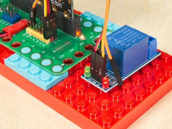
While the Bit Board V1 had a small on-board relay, it is not present on the Bit Board V2.
-
We have an old guide on using the relay on V1 (Bit Board V1 Relay) but fear not! We have a new guide on connecting an off the shelf relay to the Bit Board V2. Check out the Relay Module guide.
-
Note that due to the way a relay module functions you must use the Colored Pins (3 volts) and not the Blue Pins (5 volts). The Blue Pins really are optimized for servo usage.
-
For an example project that uses an external relay check out the Distance Bubble Machine guide.
-


After viewing the Bit Board Setup and Use video you should have the basics to get up and running with your Bit Board and start building some amazing projects!
After viewing the Bit Board Setup and Use video you should have the basics to get up and running with your Bit Board and start building some amazing projects!
