
Introduction
Use a micro:bit with a Bit Board to check if your plant needs water, and then water it using a pump activated by a Relay Module connected to the Bit Board.
This is an updated version of our older guide which used a resistive sensor: Plant Watering System (Resistive)
We recommend you use this guide which uses a Capacitive Sensor which is much more up-to-date.
Video Overview
Featured Document
-
-
In our original Moisture Sensor guide we uses a Resistive Moisture Sensor. They work okay, but are prone to corrosion with extended use.
-
The Capacitive Moisture Sensor we'll use in this guide should last much longer and will not corrode over time.
-
If you want a deeper explanation of how a Capacitive Moisture Sensor works check out these blog posts from Biomaker or Maker Portal.
-
-
-
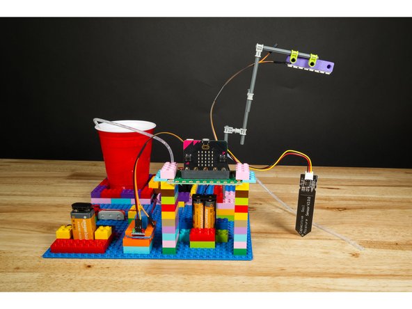
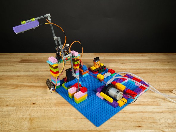
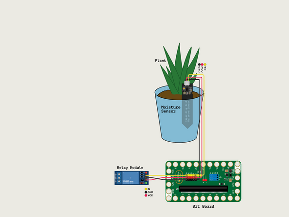
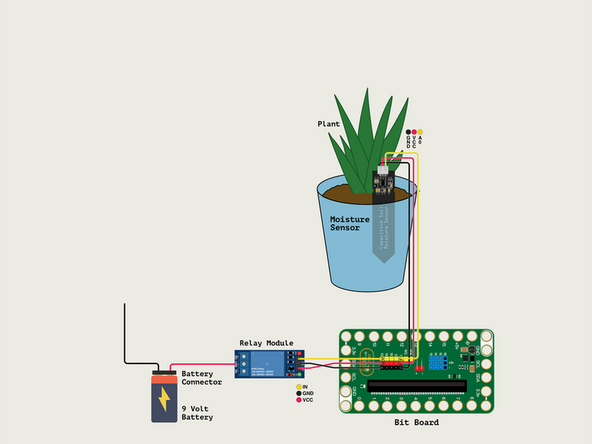
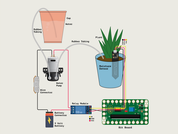
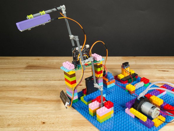
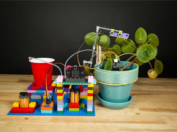
Here's the basic layout of all of the parts of our Plant Watering System. Basically, we have a plant and a container of water. There's a pump that will send water to the soil from the cup when needed.
-
We've got our Moisture Sensor stuck into the dirt of our plant. It can read how wet (or dry) the soil is.
-
The Moisture Sensor is connected to the Bit Board so the micro:bit can get a reading on the soil.
-
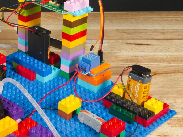
When water is needed the Relay Module will be triggered by the micro:bit so that it turns on the Water Pump.
-
We power the pump with a 9 Volt Battery. One wire goes directly to the pump using a Wire Connector, and the other goes to the Relay Module which acts as a switch.
-
We also have a Addressable RGB LED Strip (often called a "NeoPixel Strip") that can work as a light source for the plant.
-
Note: We've attached it with a NeoPixel Beam Holder
-
Finally, we can power the Bit Board with an AA Battery Pack. Note that the 9 Volt Battery is only used to power the pump.
-
-
-
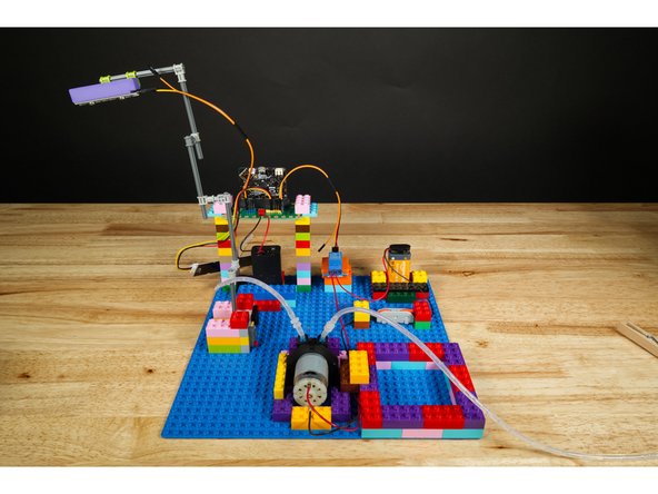
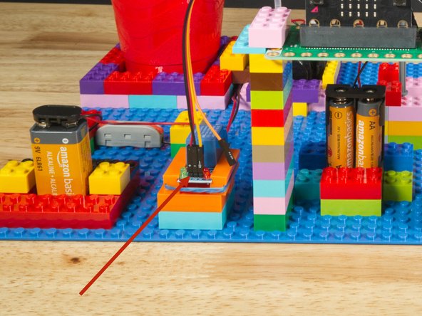
We used a large LEGO Baseplate to build our project.
-
Most of the build is just plain bricks, though we did use one of our 3D Printed Component Holders you can instead use LEGO bricks with rubber bands or tape to hold the Relay Module.
-
The Addressable RGB LED Strip is probably the trickiest part of this, so we used a bunch of random LEGO Technic axles we had lying around. (Parts list to come!)
-
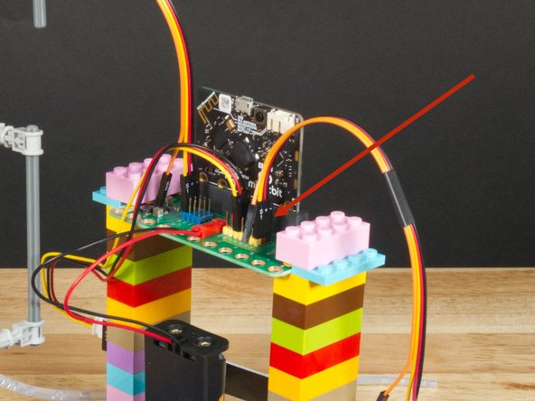
We've raised the Bit Board up on two towers of bricks so that the moisture sensor can reach our plant.
-
-
-
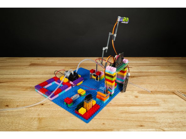
The building with LEGO is the main challenge with this project. Of course you don't have to exclusively build with LEGO.
-
You can incorporate cardboard, wooden dowels, popsicle sticks, or any other common crafting/building materials.
-
The photos of our build are mainly for reference and to provide some tips on your own build.
-
-
-
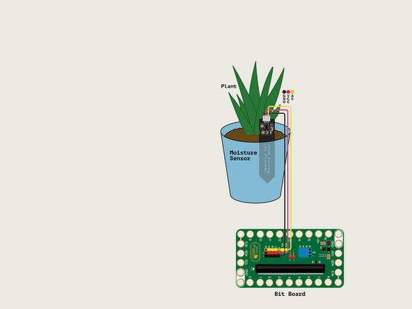
Plug the Moisture Sensor into Pin 1.
-
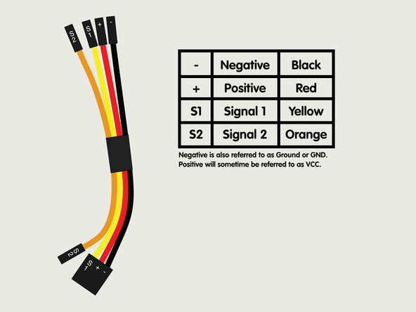
The Yellow wire will go into Pin 1.
-
The Red wire will go into the + (Positive) Pin.
-
The Black wire will go into the - (Negative) Pin.
-
We've also placed the Moisture Sensor into the dirt of our plant.
-
-
-
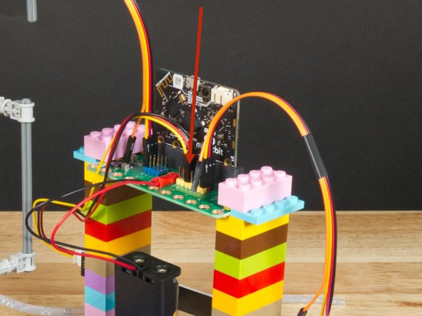
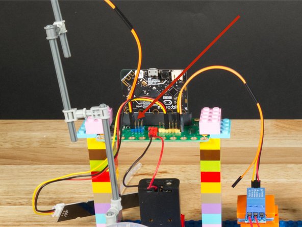
Before we add the Relay Module we'll start by plugging a Crazy Circuits Ribbon Cable into Pin 13.
-
Since the Crazy Circuits Ribbon Cable has a connector on one end that combines three wires together you'll want to plug that end into the Bit Board. The Yellow wire will get plugged in and the Orange wire will be dangling on its own.
-
Note: You don't have to use a Crazy Circuits Ribbon Cable and can certainly use any F/F Jumper Wires but the color-coded Crazy Circuits Ribbon Cable with the end connector makes things a little easier for beginners.
-
-
-
Let's plug in the Relay Module! (Again, if you're using the Crazy Circuits Ribbon Cable it makes things a little easier, but any F/F Jumper Wires will work fine.)
-
The Red wire will go into the VCC Pin.
-
The Black wire will go into the GND Pin
-
The Yellow wire will go to the IN Pin.
-
VCC stands for Voltage Common Collector and is often used to indicate where Positive power is applied in a circuit.
-
IN is often used to indicate an INPUT and it is how we control the circuit using the micro:bit
-
-
-
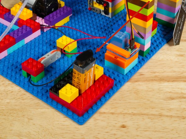
Attach the 9 Volt Battery Connector to the 9 Volt Battery.
-
We built a little LEGO brick "pocket" to fit the battery into, but you can attach it in any way you like.
-
-
-
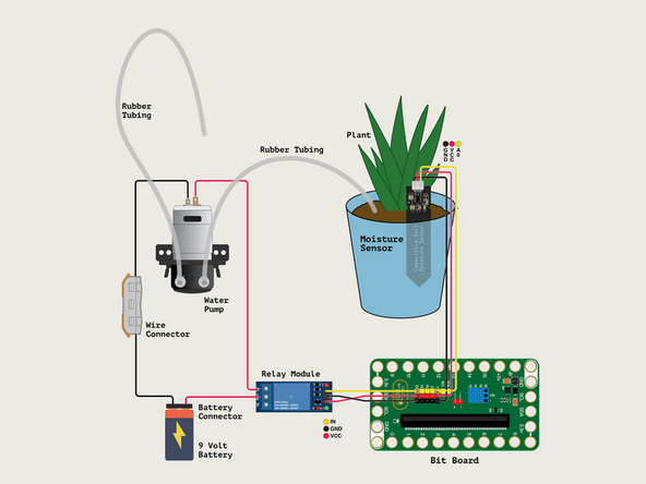
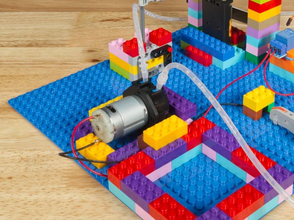
We'll add the Water Pump next. The pump needs to be connected to the 9 Volt Battery for power.
-
The Relay Module sits between the Battery and the Pump and acts as a "Smart Switch" to turn on the pump by closing the circuit when the micro:bit tells it to.
-
The Red (Positive) wire from the battery connector will go to the COM (Common) Screw Terminal on the Relay Module.
-
The Red (Positive) wire from the Pump will go to the NO (Normally Open) Screw Terminal on the Relay.
-
We will then run the Black (Negative) wire from the battery connector to the Black (Negative) wire of the Pump. We're going to use a Wire Connector to make the connection.
-
If you don't have a Wire Connector you can twist the bare wires together and cover with a small piece of masking tape or other non-conductive tape.
-
-
-
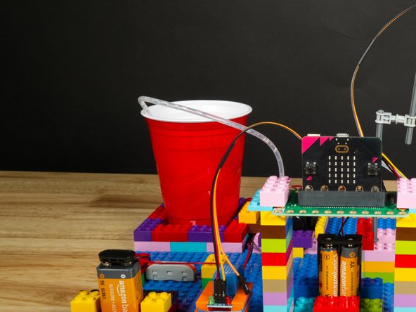
Once we have the Water Pump connected we can place the feed hose into our water container.
-
We used a red plastic cup for our demo, and we built up a little wall of LEGO bricks around it to help hold it in place.
-
You may want a more stable water container. An old food container with a lid you can cut notches out of for the wire and tubing would be ideal.
-
Warning! Water and electronics do not mix! While the Moisture Sensor is meant to be in wet soil, water should not touch other parts of your electronics. Be careful around the wires, battery, relay, Bit Board, and any other components.
-
-
-
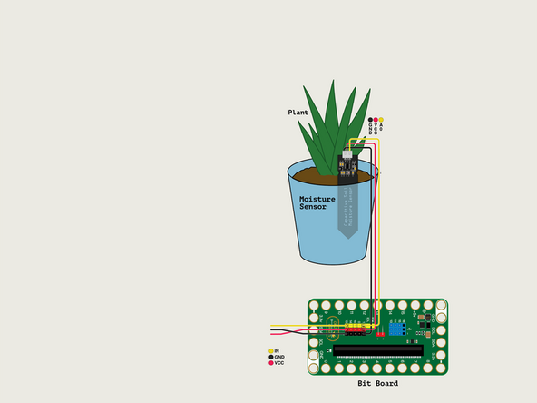
Let's plug in the Addressable RGB LED Strip! (Again, if you're using the Crazy Circuits Ribbon Cable it makes things a little easier, but any F/F Jumper Wires will work fine.)
-
The Red wire will go into the VCC Pin.
-
The Black wire will go into the GND Pin
-
The Yellow wire will go to the IN Pin.
-
Plug the other end of the Crazy Circuits Ribbon Cable into Pin 16 of the Blue Pins.
-
-
-
If you've never used a micro:bit before you'll want to check out this guide: Bit Board V2 Setup and Use
-
We're going to load the following code for our Plant Watering System V3 program: https://makecode.microbit.org/_XxXCfDAme...
-
Don't run the code immediately! It's best to disconnect the 9 Volt Battery so we don't start pumping water until after we calibrate the system.
-
-
-
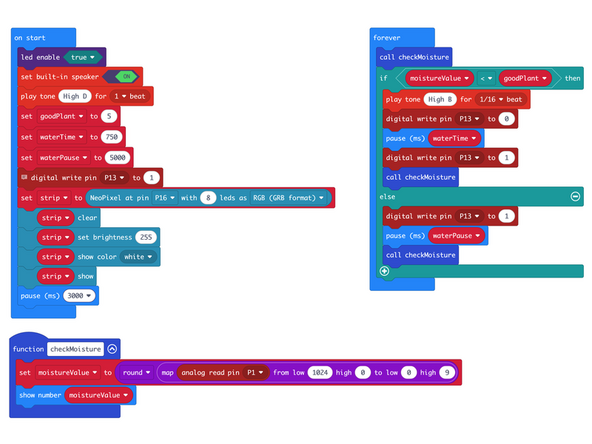
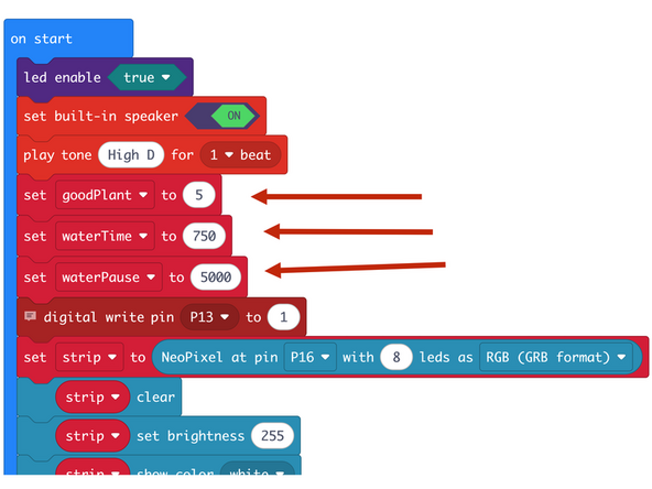
There are two variables you can adjust in the on start section of the code.
-
The goodPlant variable is the number the Moisture Sensor will read from the soil. The scale goes from 0 to 9 and for our plant 5 or 6 was properly moist soil.
-
The waterTime is the amount of time the pump will run to put water into the soil. 1000 milliseconds = 1 second, so this will run for 1 second, then check the sensor again, and add more water if still needed.
-
We'd recommend starting with the waterTime variable set to 1000 or lower, as we don't want to overdo it and add too much water.
-
Finally, the waterPause is the amount of time between water being pumped to the plant.
-
-
-
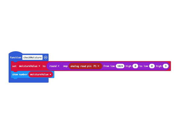
We use a function named checkMoisture to read the Moisture Sensor connected to Pin 1 and determine the value. (We also display the value on the micro:bit)
-
The value will be between 0 and 1024 with 0 being wet and 1024 being dry.
-
Since we want to use a scale of 0 to 9 take make it easy to display (with 0 being dry and 9 being wet) we'll use the map function to remap the scale of the values and to reverse it.
-
So if the sensor reads a value of 1024 we'll map that to 0 and if the sensor reads a value of 0 we'll map that to 9.
-
If our sensor reads a value near 512 that will map to either 4 or 5 on our scale.
-
We've also added the round function so if we get a decimal reading such as 4.3 it will display as 4 on the micro:bit's built-in LED matrix. Otherwise it would scroll 4.3 across the display, making it much more difficult to read the value quickly.
-
-
-
We are ready to calibrate!
-
First, disconnect the 9 Volt Battery to prevent the pump from running while we get some measurements.
-
If you've got the code loaded, and the sensor in the soil, power up the Bit Board with the battery pack and after a few seconds you should see a value on the LED matrix.
-
We got a value of 3 which means our soil is a bit dry!
-
We added what we thought was the correct amount of water and the value went to 5. This is how we got the value we set the variable goodPlant to, which you can see in Step 13.
-
-
-
If everything seems to work so far you can reconnect the 9 Volt Battery and test the whole system.
-
If you want to "trick" your probe into thinking the soil is dry just pull it out of the soil and the value should go low enough to cause the pump to run.
-
Remember! You will need to experiment to determine how much water your plant needs, how often you should check the soil, etc. Gather information and make decisions based on what you've learned.
-
-
-
Like many of our projects, we are working with a cause and effect, and we're using a sensor to collect data and do something based on that input.
-
You might want to experiment with placing the probe in different places to see what readings you get.
-
You can also change the code to do other things or alter the behavior of the system. Anything goes!
-


Attached Documents
