Introduction
If you've built our Rover Main Body this is a great accessory. A slightly more advanced built Claw than can attach to the front of the Rover and take your Rover to new exciting levels.
Parts
Video Overview
Featured Document
-
-
The Claw is an optional, more advanced attachment to the Bit Board Rover. If you haven't built the Gripper, Lifter or Sweeper yet those are great attachments that are an easier build and a good starting point.
-
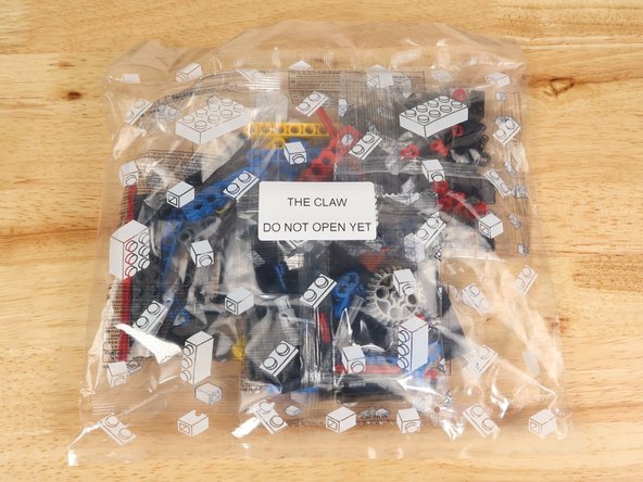
To build the Claw, you will need the bag of parts pictured, the gray 270° servo from the Rover kit and a completed Bit Board Rover.
-
The Claw is included in the Bit Board Rover kits as of February 2026. If you have an older kit and would like to purchase the parts to build The Claw you can purchase that here: The Claw.
-
The Claw bag has three individual bags inside. They are not organized in a specific way. Just open all three and jump in!
-
-
-
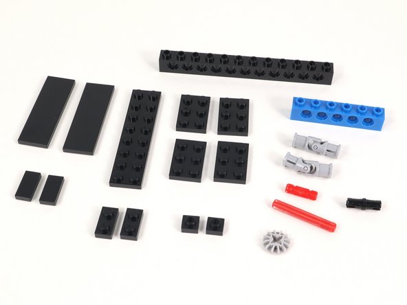
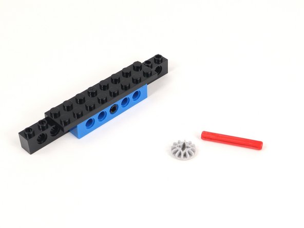
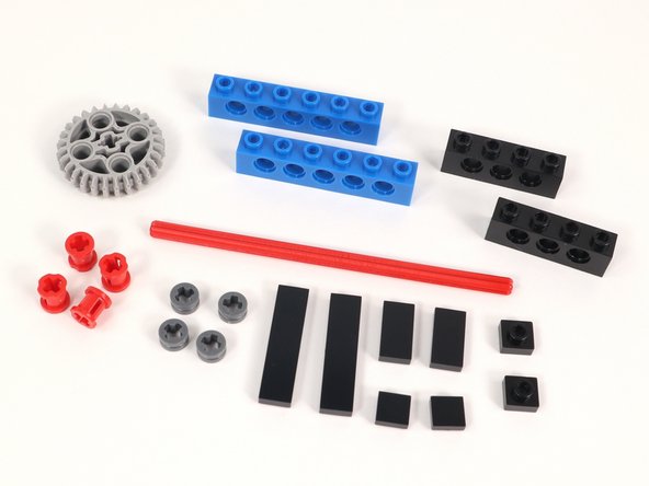
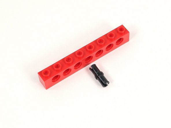
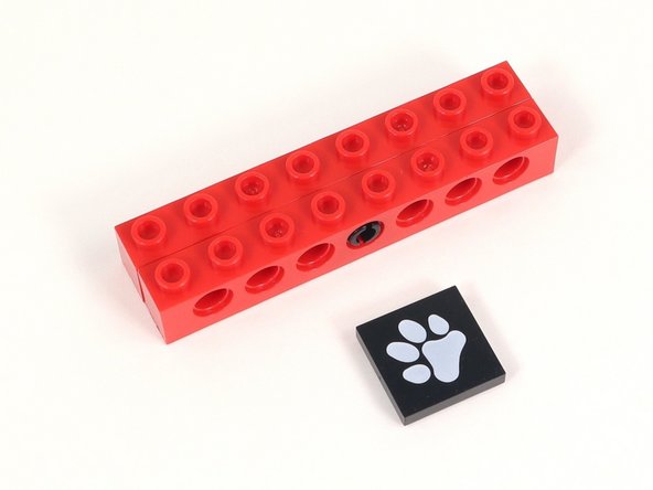
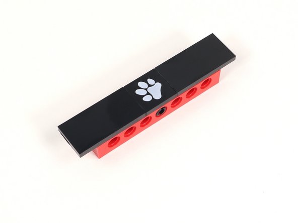
The main build is broken down into three sections. These are the parts you will need for Section 1.
-
-
-
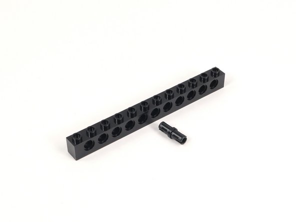
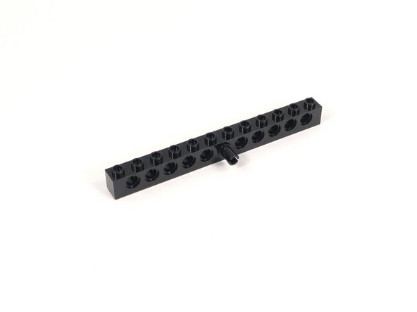
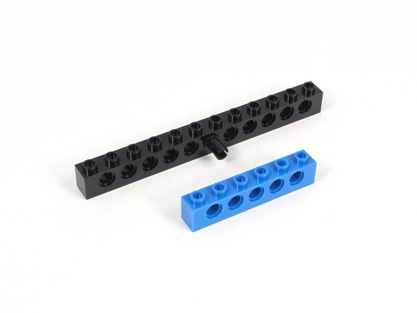
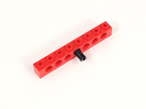
Add a black pin to the center hole of the 1x12 brick with holes.
-
-
-
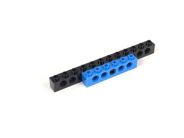
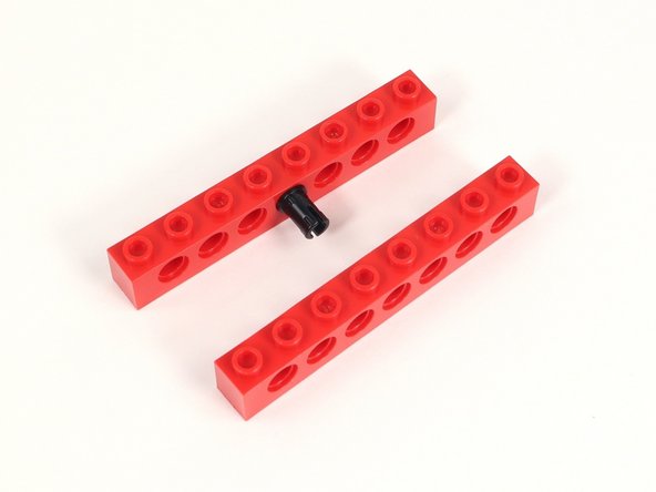
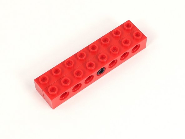
Connect the black pin through the middle hole of a 1x6 brick with holes.
-
-
-
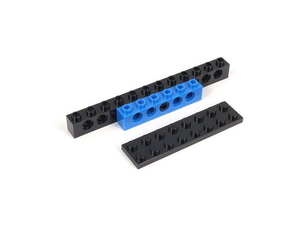
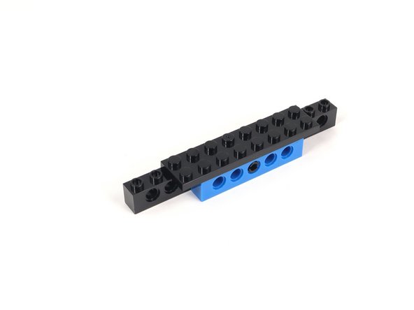
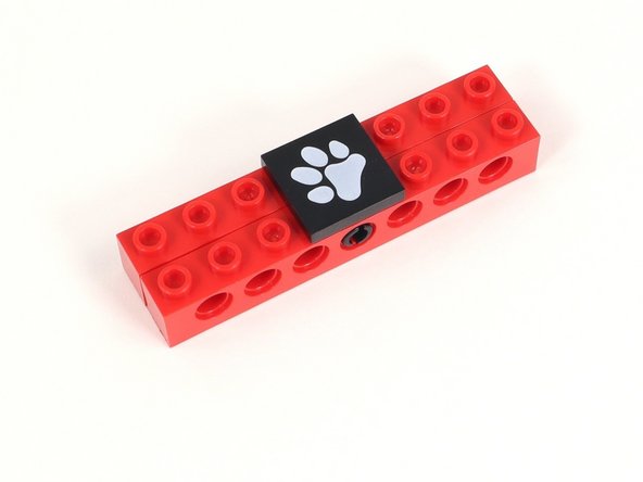
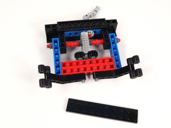
Attach a 2x8 plate on top of section 1 in the center, leaving 2 studs on either side open.
-
-
-
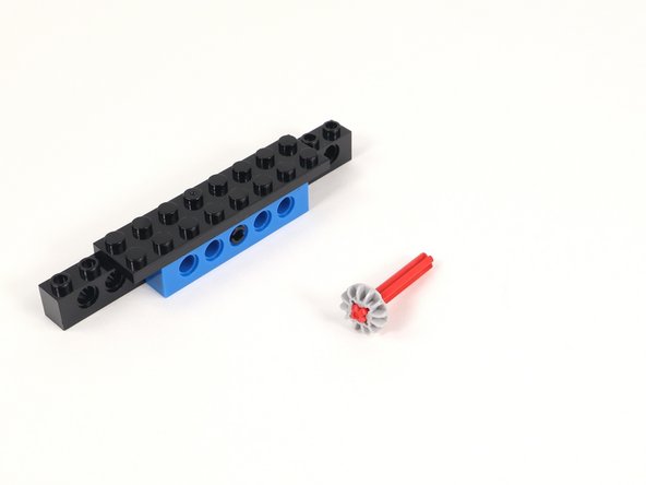
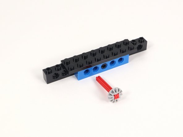
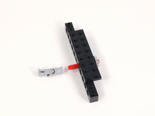
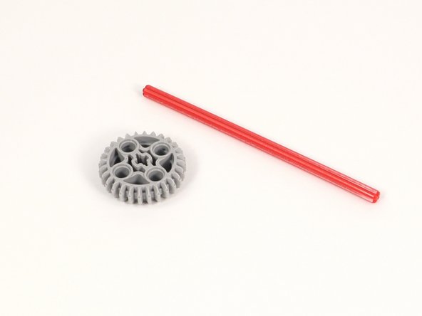
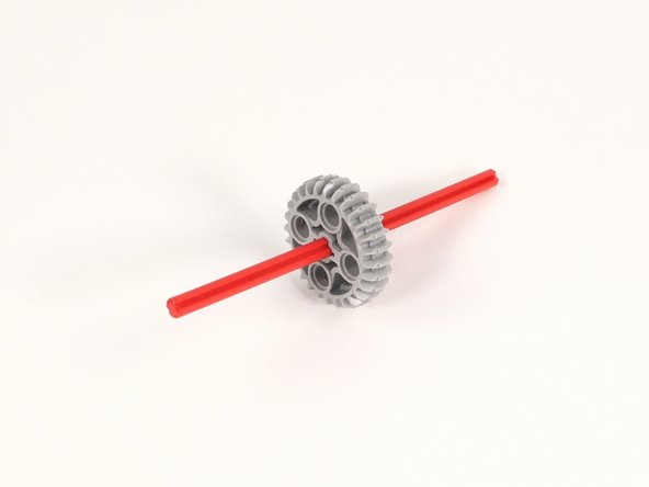
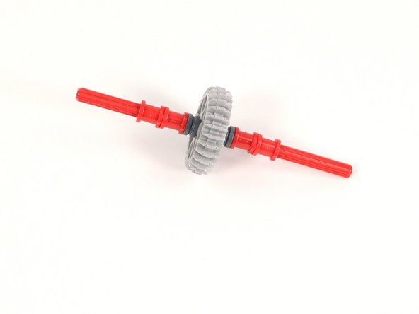
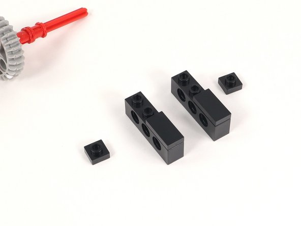
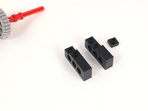
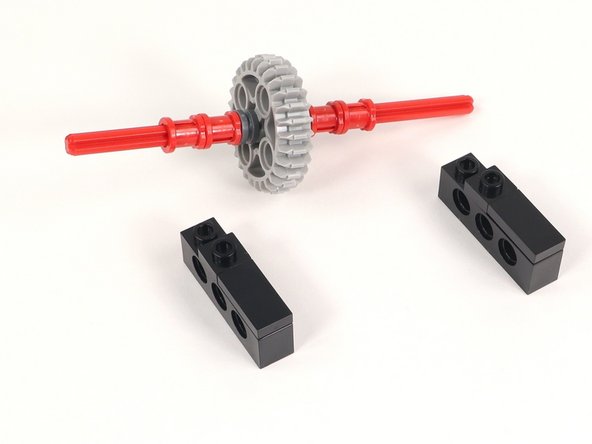
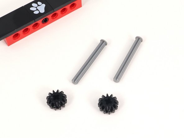
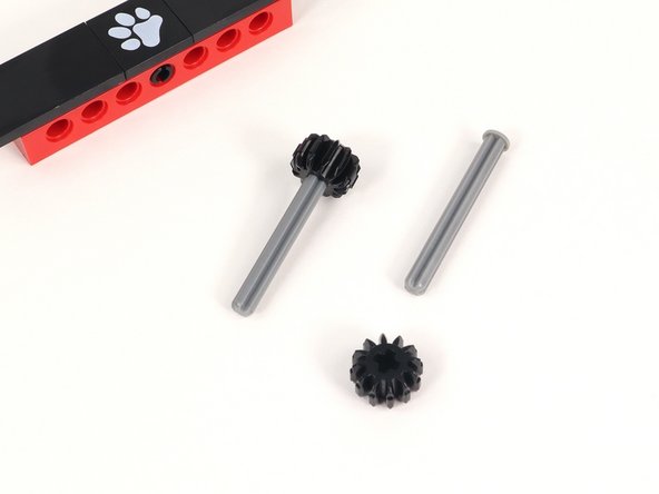
Connect the small gray gear to the end of the 4 stud long red axle.
-
The gear only has teeth on one side. Make sure the teeth are facing outward towards the end of the axle.
-
-
-
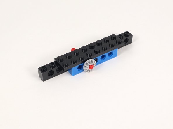
Insert the axle into the hole to the left of the hole with the black pin.
-
-
-
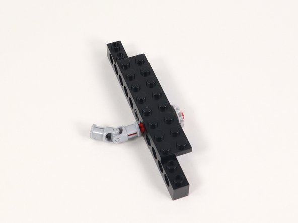
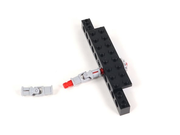
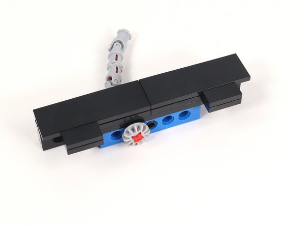
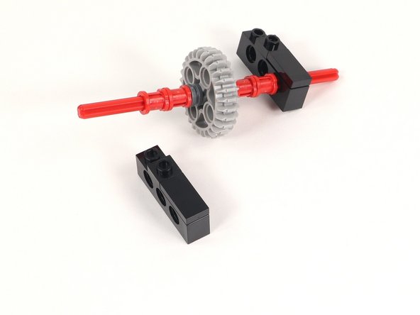
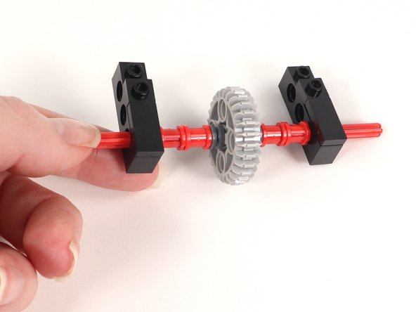
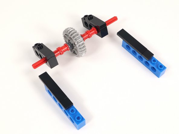
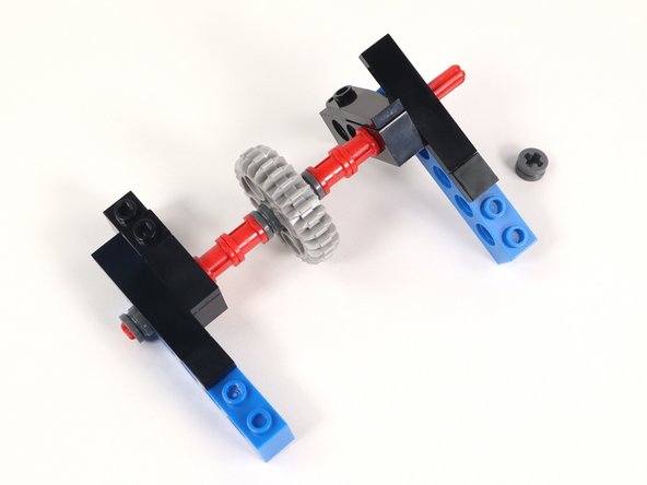
Connect one end of a universal joint onto the end of the axle opposite the gear.
-
-
-
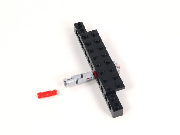
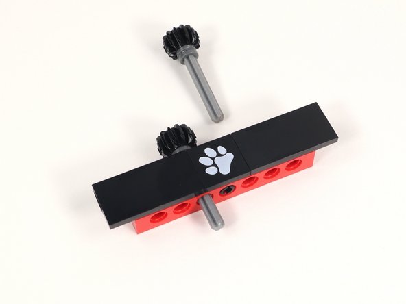
Insert a 2-stud long axle into the other end of the universal joint.
-
-
-
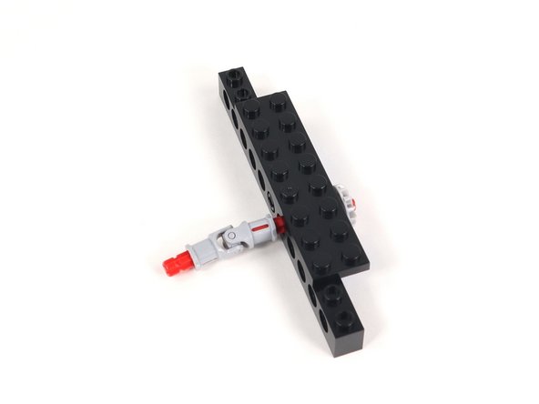
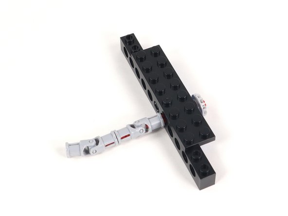
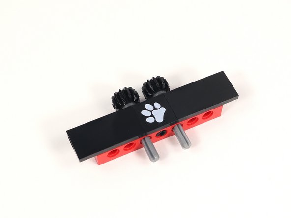
Connect a second universal joint to the other end of the axle.
-
-
-
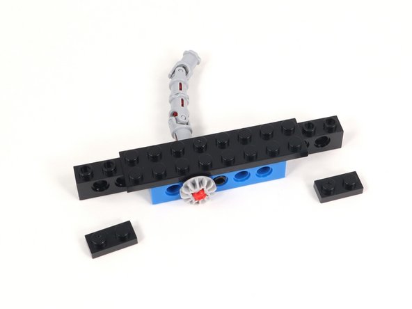
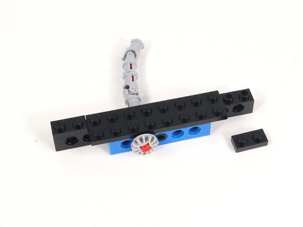
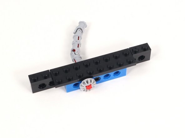
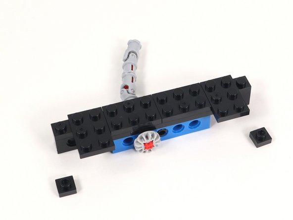
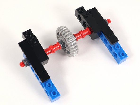
Add 1x2 plates to each end of the 1x12 brick with holes.
-
-
-
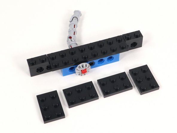
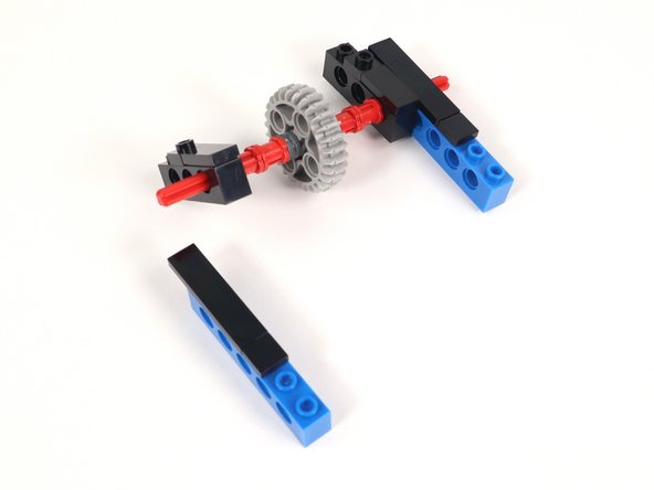
In this step you will add 4 2x3 plates. Two of them will attach horizontally, following the direction of the build. The other two will stick off the front of the section toward the gear side. These will help us connect Section 1 to Section 2 in a later step.
-
Attach (2) 2x3 plates in the center of Section 1 so they line up with the blue brick with holes.
-
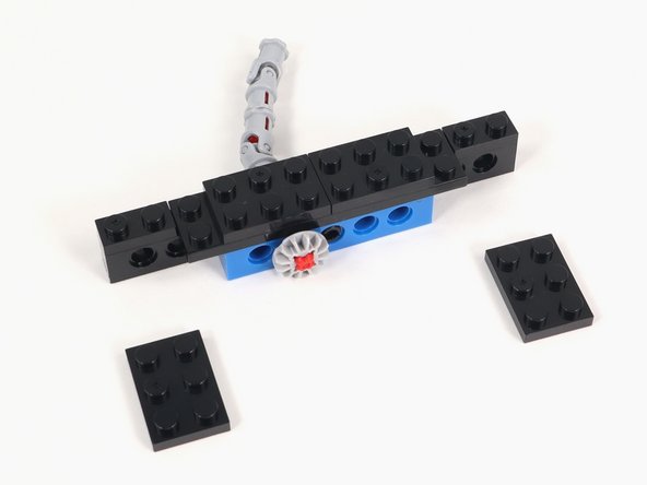
Attach the other (2) 2x3 plates sticking off the front of the build toward the gear side. They should only connect to three studs.
-
-
-
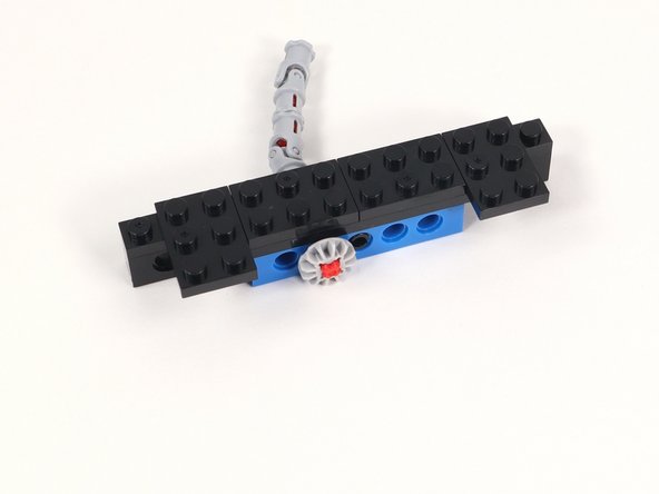
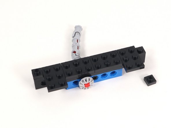
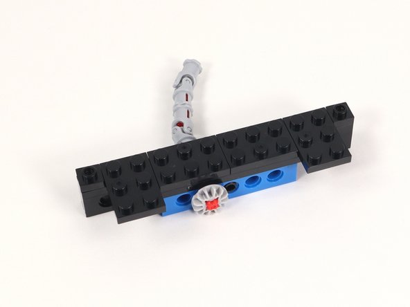
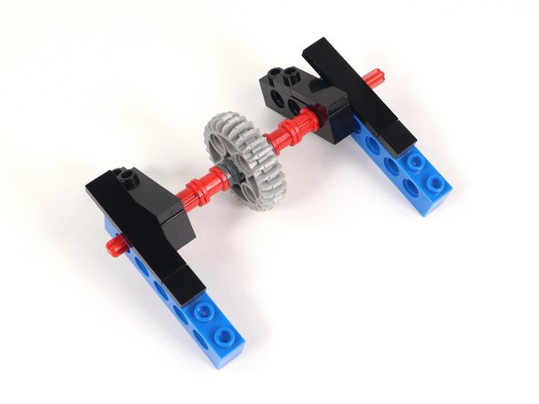
Add a 1x1 plate to each end of the build.
-
-
-
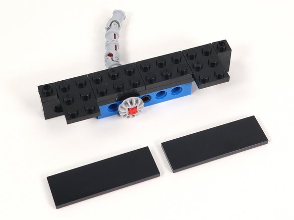
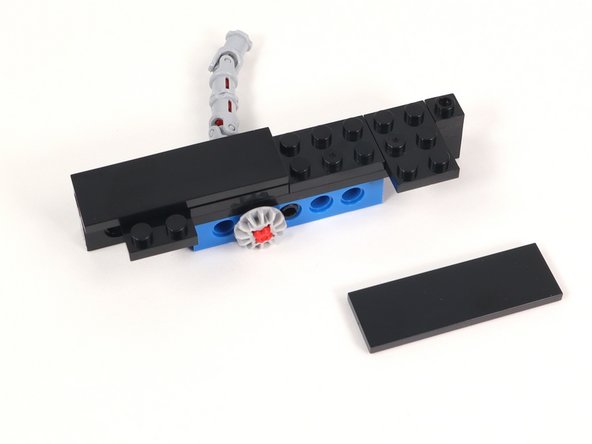
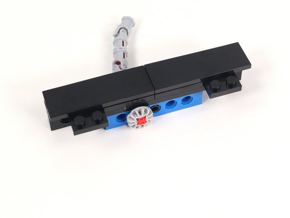
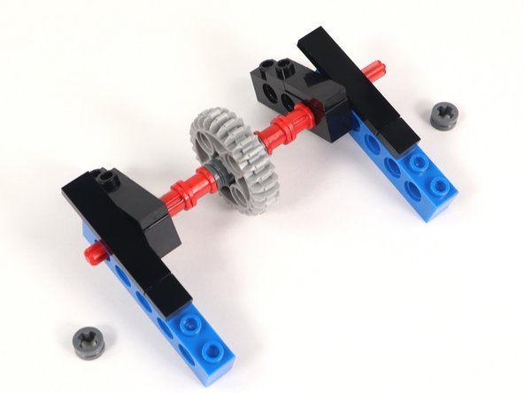
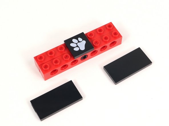
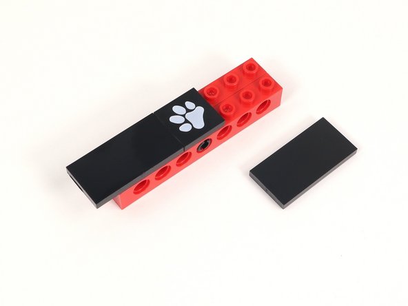
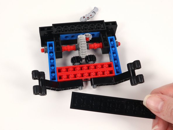
Add (2) 2x6 tiles to cover the top of Section 1.
-
-
-
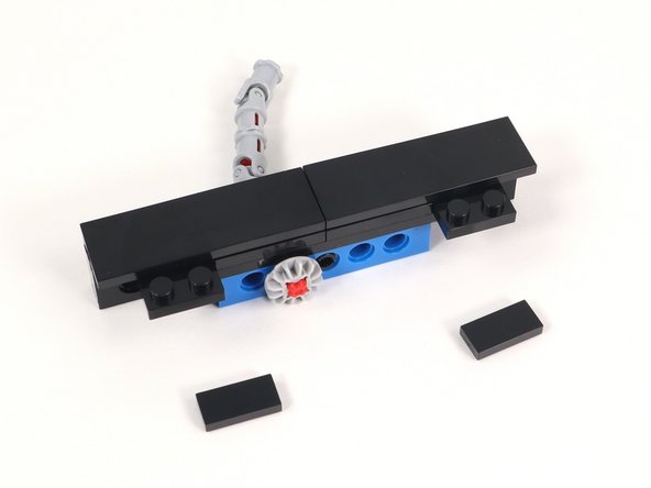
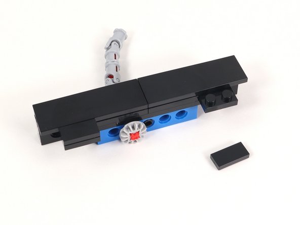
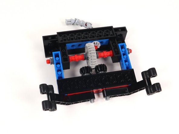
Add (2) 1x2 tiles to the remaining exposed studs on Section 1.
-
-
-
Gather the parts you will need for Section 2.
-
-
-
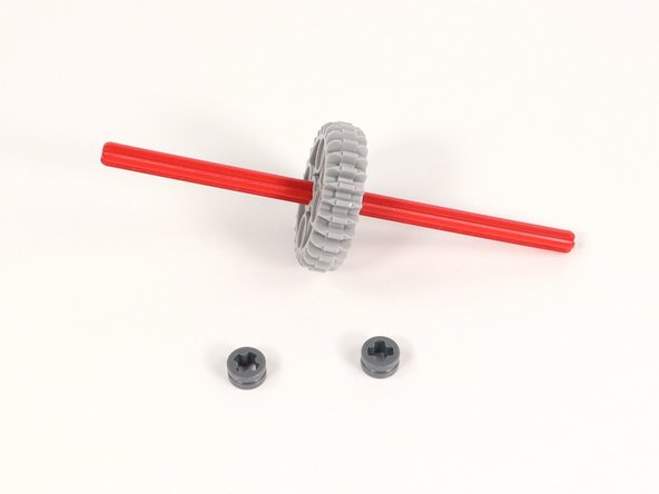
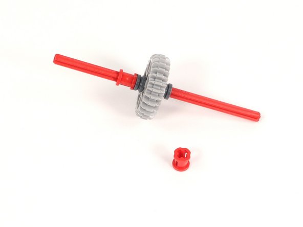
Add the large gear to the center of the 12-stud long axle.
-
-
-
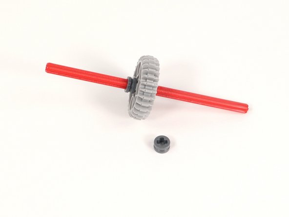
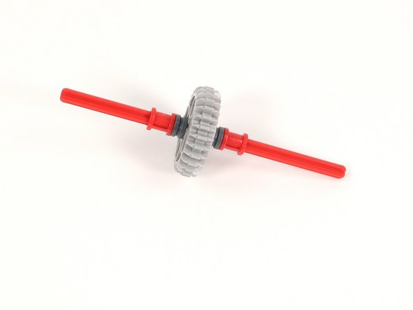
Add a half bushing to each side of the large gear.
-
-
-
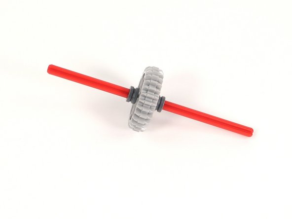
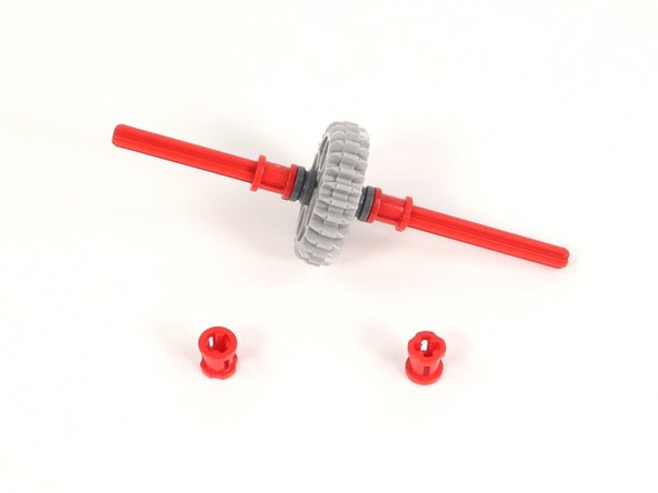
Add a full bushing to each side of the large gear.
-
-
-
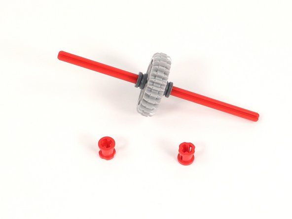
Add another full bushing to each side of the large gear.
-
-
-
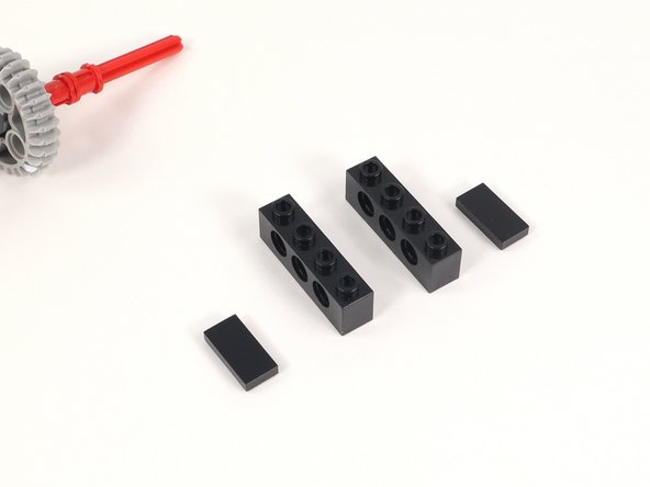
Add a 1x2 tile to the last two studs of a 1x4 brick with holes. You will need two of these.
-
-
-
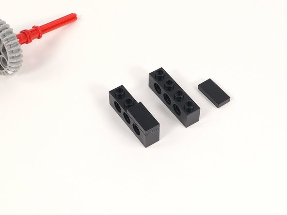
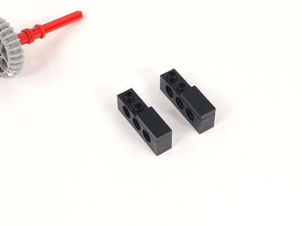
Add a 1x1 plate to each 1x4 brick with holes adjacent to the 1x2 plate added in the previous step.
-
-
-
Slide one of the 1x4 brick with holes onto each end of the axle.
-
The axle should be through the first hole (under the 1x2 tile).
-
-
-
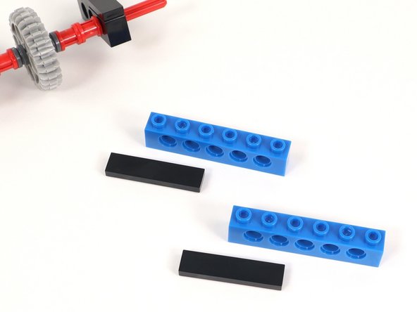
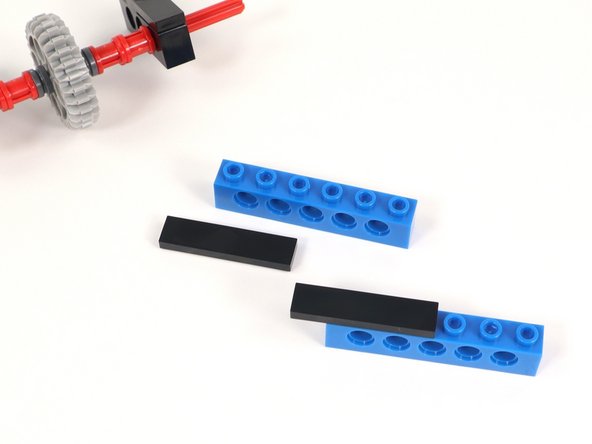
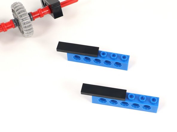
Add a 1x4 tile to the three studs on one end of a 1x6 brick with holes. You will need two of these.
-
One stud of the the tile will stick off the end of the brick. You should have three studs still exposed.
-
-
-
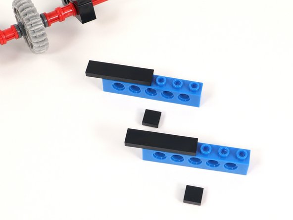
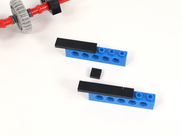
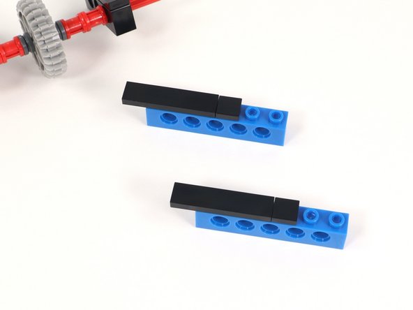
Add a 1x1 tile on the next open stud of each brick.
-
-
-
Add the bricks with holes to each side of the axle. The axle should go through the very last hole under the 1x4 tile.
-
Since the bricks with holes can swing around the axle, pay attention to photo three to assure your build is accurate.
-
-
-
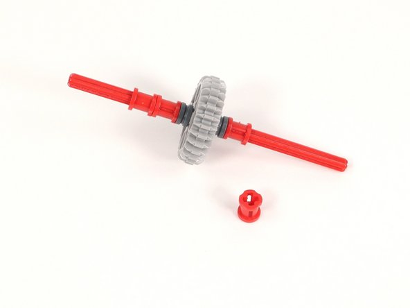
Add a half bushing to each end of the axle to hold everything in place.
-
The bricks may spin around the axle at this point. Do not worry about that since we will address it when we connect Section 1 and Section 2.
-
-
-
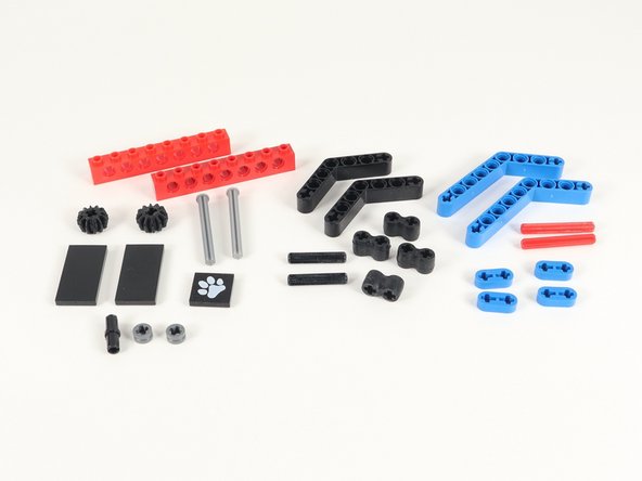
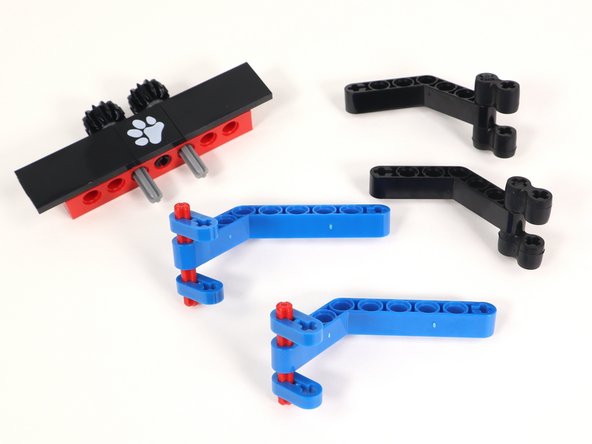
Gather the parts you will need for Section 3.
-
There are two different build options for the arms. With the pieces you have you can build both options and change them up as you would like. Option 1 has the black bent beams and Option 2 has the blue bent beams.
-
-
-
Add a black pin to the center hole of a 1x8 brick with holes.
-
-
-
Add a second 1x8 brick with holes to the other side of the black pin.
-
-
-
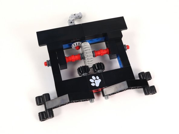
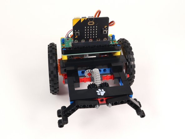
Add the 2x2 tile with a paw print to the middle four studs of the build.
-
-
-
Add a 2x4 tile on either side of the paw print tile. Each of those tiles should hang off the build by one column of studs.
-
-
-
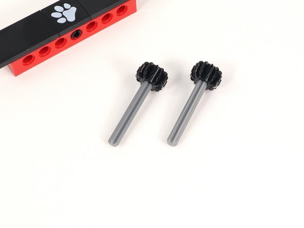
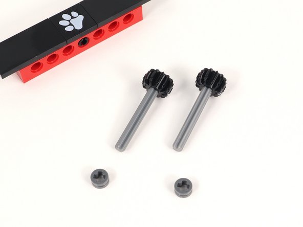
Add a small black gear to an axle with end stop and push it all the way down to the end stop. You will need two of these.
-
-
-
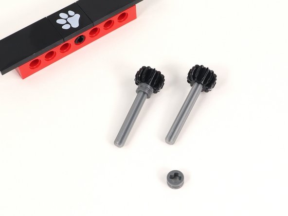
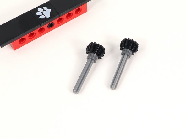
Add a half bushing to each axle and push it all the way down to the gear.
-
-
-
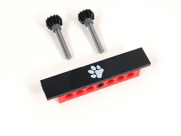
Insert the axles through the holes to the left and right of the center hole (that has a black pin in it) from the back so the open end of the axle is facing the front.
-
-
-
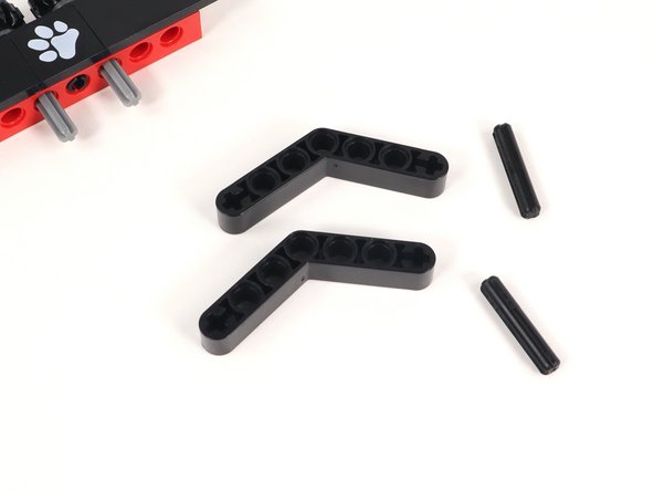
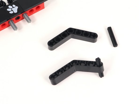
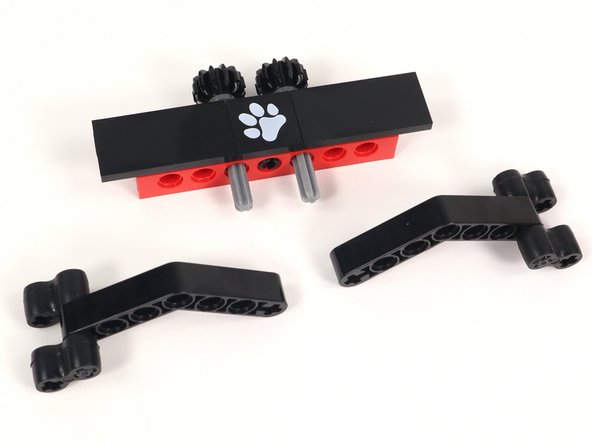
There are two different options for arms on the Claw attachment. These are the steps for option 1.
-
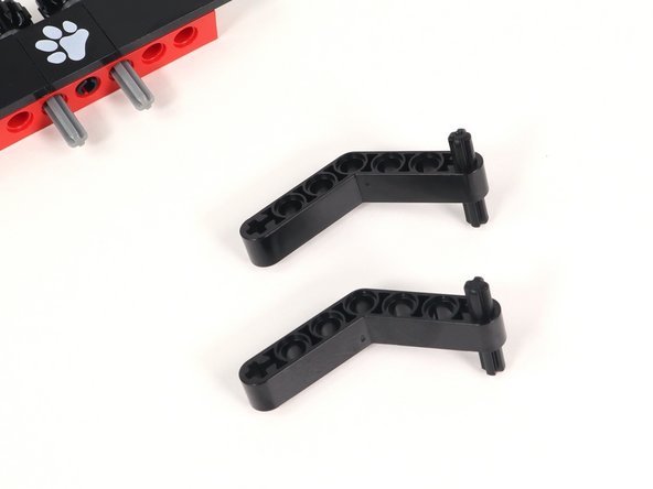
Insert a 3 stud long black axle into the plus-shaped hole at the end of a black bent beam. You will need two of these.
-
-
-
There are two different options for arms on the Claw attachment. These are the steps for option 1.
-
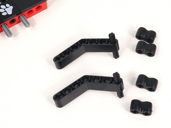
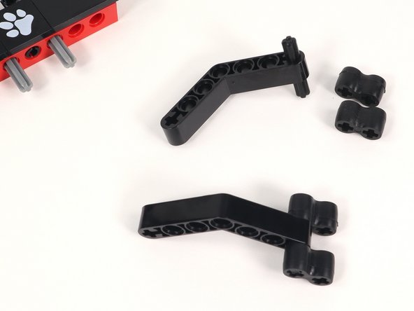
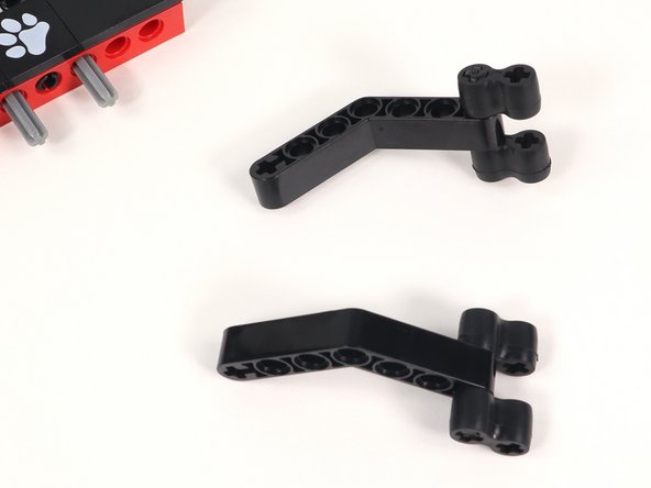
Attach a rubber gripper to each end of the axle on both grippers as pictured. These can be adjusted when using depending on what you are trying to grab.
-
-
-
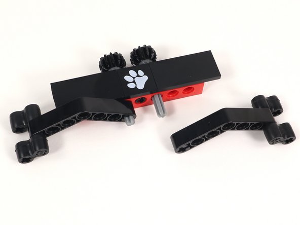
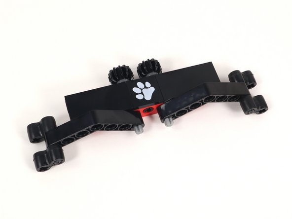
There are two different options for arms on the Claw attachment. These are the steps for option 1.
-
Connect the Claw arms to the axles on Section 3.
-
-
-
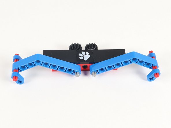
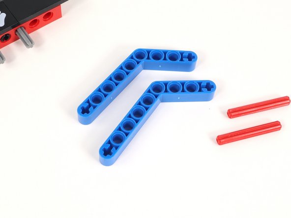
There are two different options for arms on the Claw attachment. These are the steps for option 2.
-
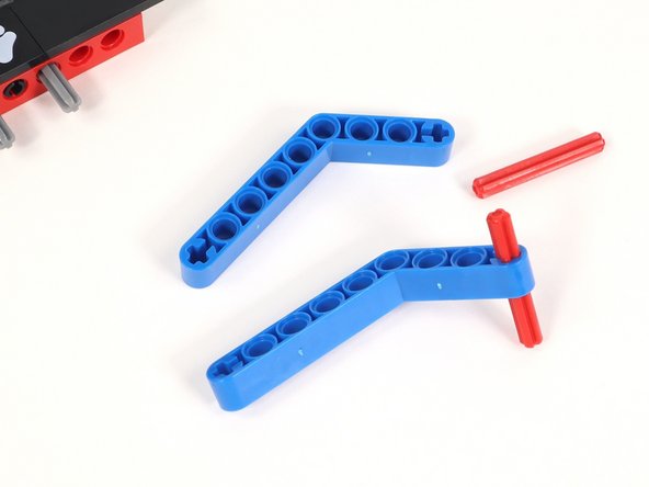
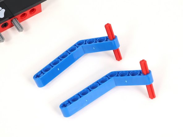
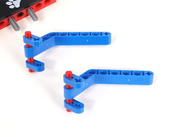
Insert a 4 stud long red axle into the plus-shaped hole at the end of the short side of a blue bent beam. You will need two of these.
-
Since the bent blue beam is not the same length on each side, you can play around with the placement of the axle based on your needs.
-
-
-
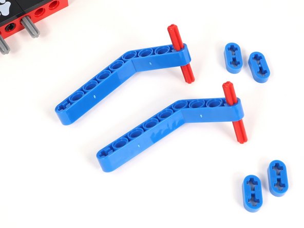
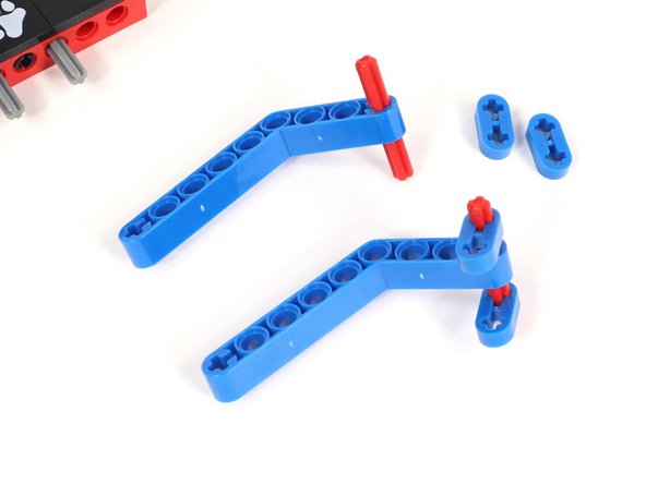
There are two different options for arms on the Claw attachment. These are the steps for option 2.
-
Attach a blue plastic 0.5 beam to each end of the axle on both grippers. These can be adjusted when using depending on what you are trying to grab.
-
-
-
There are two different options for arms on the Claw attachment. These are the steps for option 2.
-
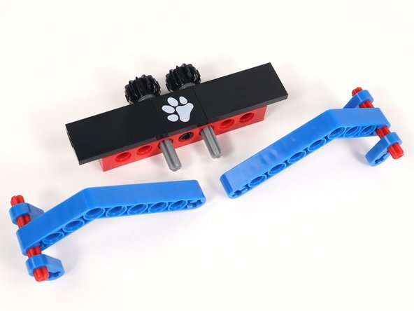
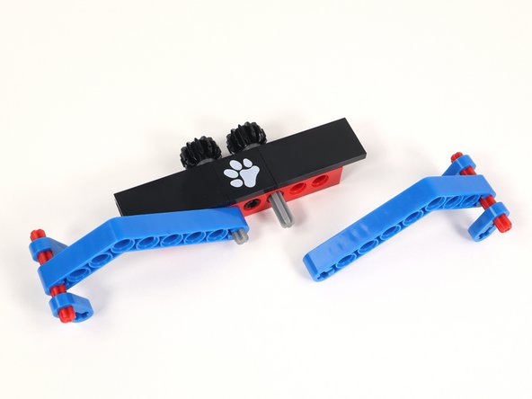
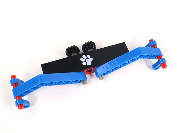
Connect the Claw arms to the axles on Section 3.
-
-
-
Both sets of Claw arms are interchangeable. Do you have a task that needs something different? Change it up or use different pieces that don't come in this kit.
-
You could even 3D print a completely new attachment for your Claw. The possibilities are endless!
-
-
-
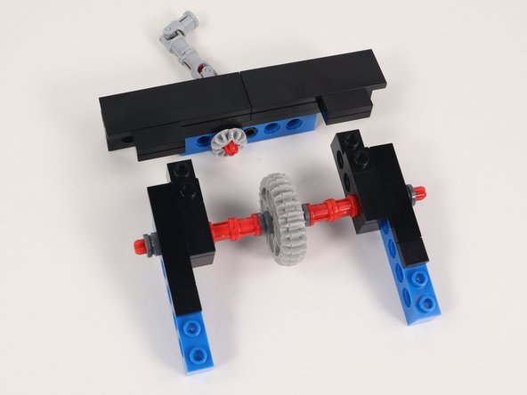
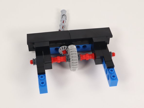
Connect Section 1 and Section 2 by lining up the gears so they interlock and the two open studs on Section 2 snap in place to the bottom side of Section 1.
-
It this point, when turning one gear the other should turn as well.
-
-
-
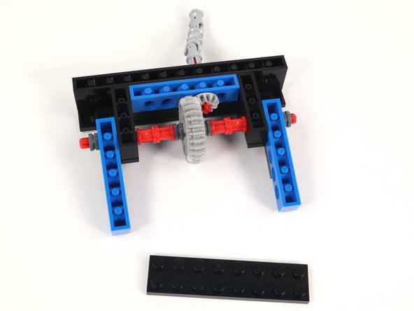
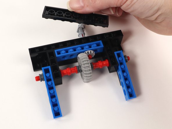
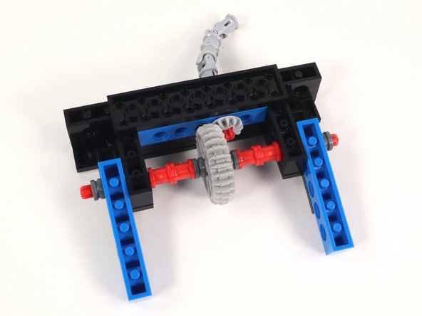
Now that you have connected Section 1 and Section 2 flip the build over and add a 2x8 plate to the bottom center of the build. This will help keep the sections together.
-
-
-
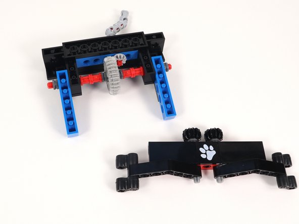
With Section 1/2 still flipped upside down, take Section 3 and also flip it upside down.
-
Make sure that the Claw arms are laying out to the sides. This will help ensure that they are aligned correctly with one another once the gears connect.
-
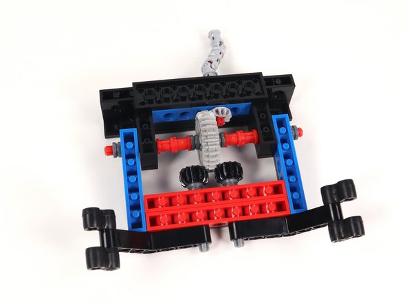
Connect the two sections by inserting the open studs on the blue bricks with holes to the bottom of the black tiles on Section 3. Check to make sure that the teeth on the black gears mesh with the large gear.
-
-
-
Add a 2x10 plate to the bottom of the build to reinforce the connection of the sections.
-
-
-
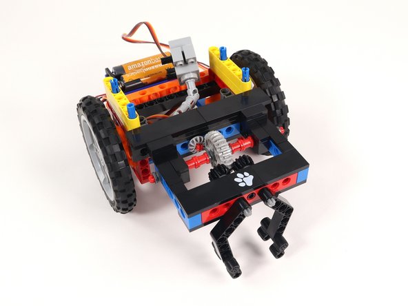
You have completed the Claw attachment build! Now we need to make modifications to the Bit Board Rover so we can connect them.
-
If you do not have a completed Bit Board Rover in hand, follow the directions and build one before proceeding.
-
-
-
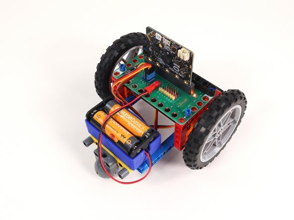
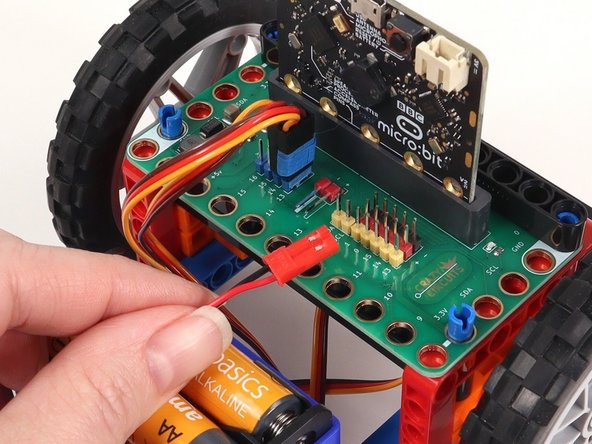
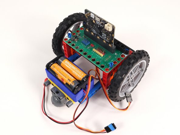
On the back of the Rover disconnect the battery pack and both servos from the Bit Board.
-
-
-
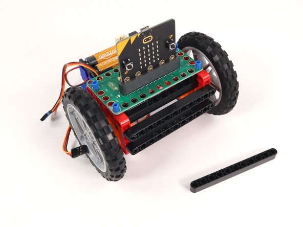
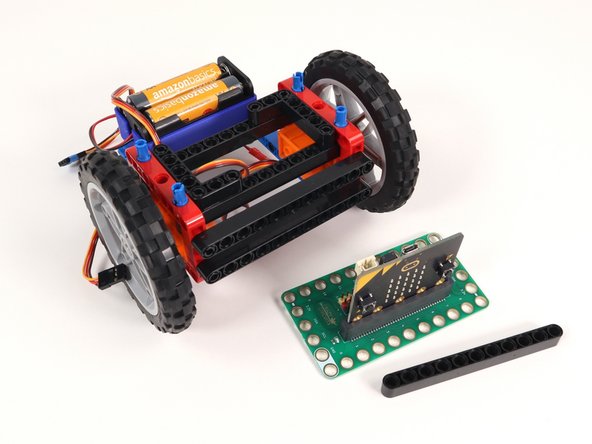
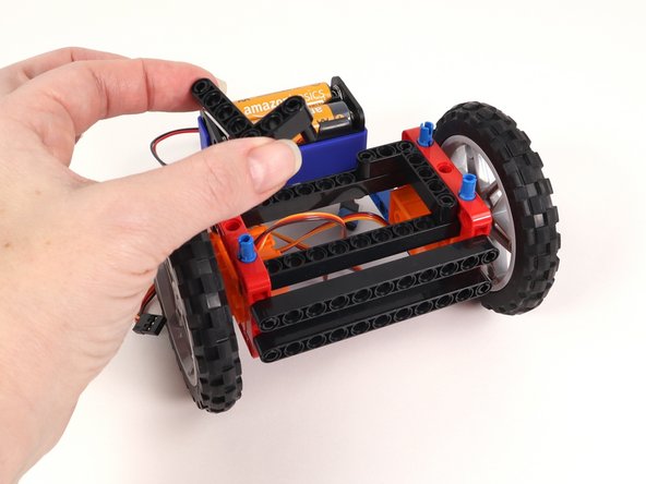
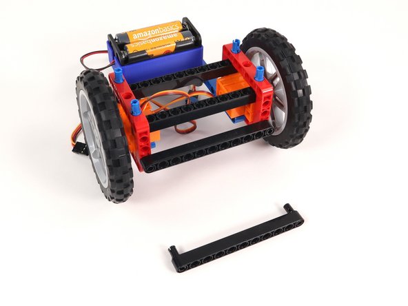
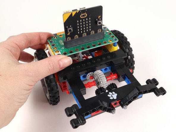
Remove the long black beam anchoring the Bit Board in place on the front of the Rover.
-
Remove the Bit Board and MicroBit from the Rover.
-
Set the black beam, MicroBit, and Bit Board aside. We will add these back in a later step.
-
-
-
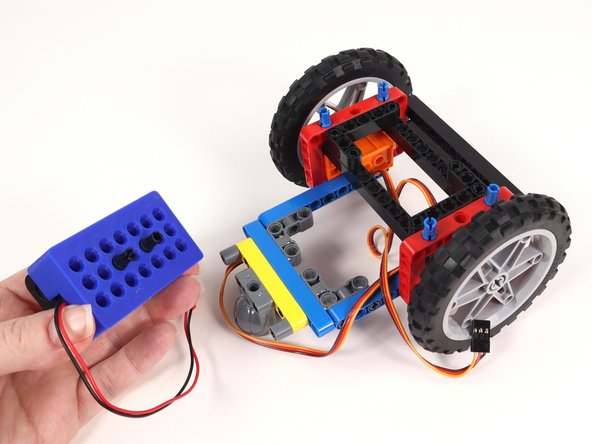
Remove the battery pack from the back of the Rover.
-
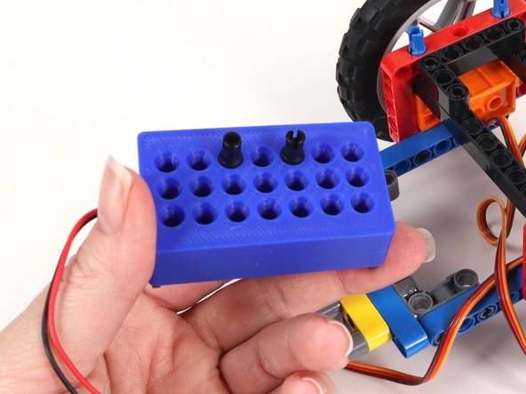
Adjust the location of the two black pins on the bottom of the battery pack. They should be moved to the top row with an empty hole in between them.
-
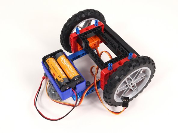
Reattach the battery pack to the Rover. All this did was move the battery pack farther back on the Rover so we can fit a motor on the build for the Claw.
-
-
-
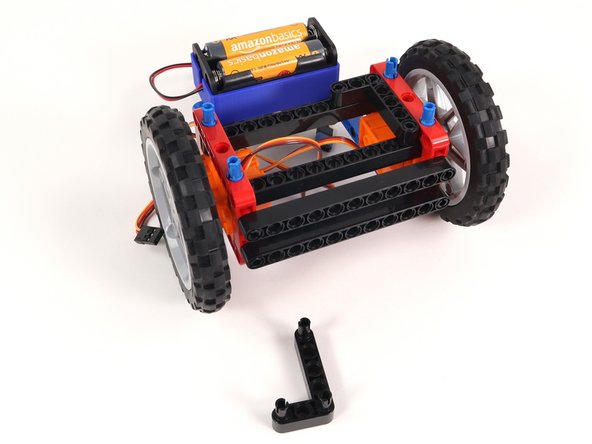
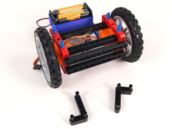
Remove both L-shaped beams and the 3 pins holding them in place.
-
-
-
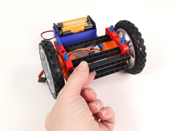
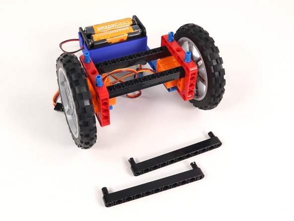
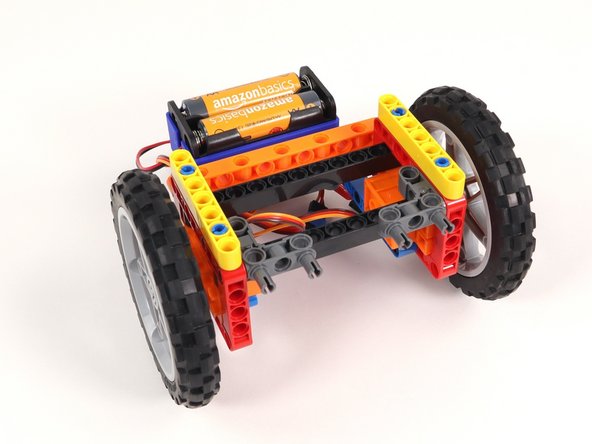
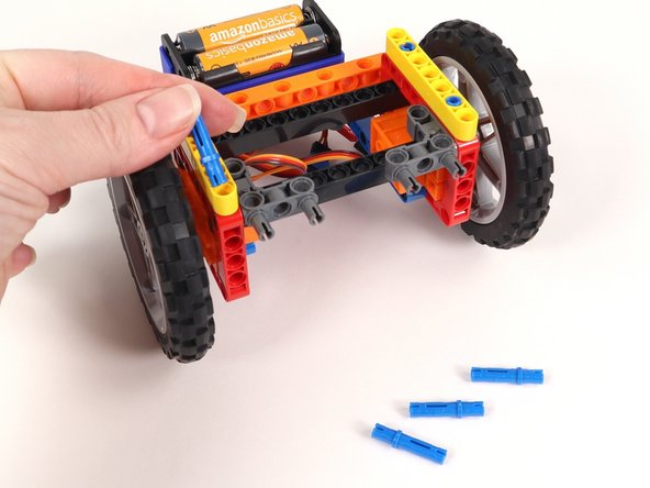
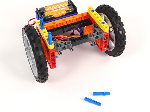
Remove the two long black beams on the front of the Rover as well as the black pins holding them in place.
-
-
-
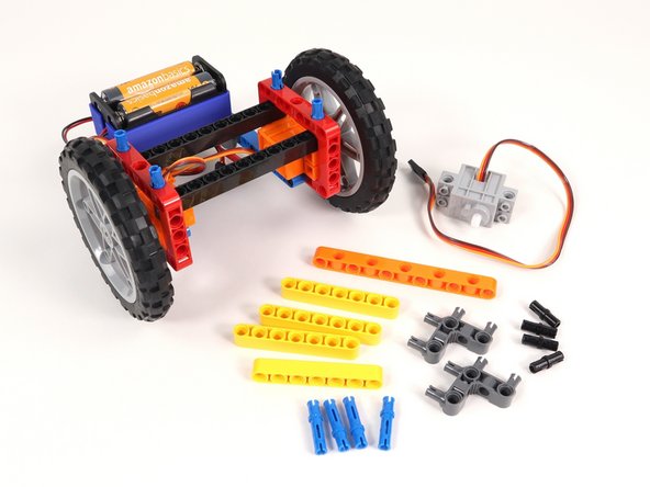
Gather the new parts that will need to be added to modify the Rover.
-
The gray 270° servo is the one that is used for the Gripper, Sweeper, and Lifter.
-
-
-
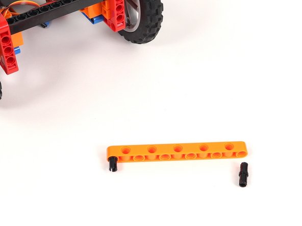
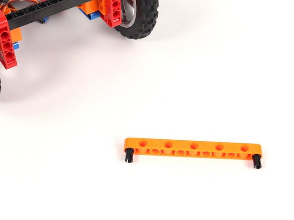
Add black pins to the first and last holes on the orange beam with side holes.
-
These pins should be on the side with 6 holes.
-
-
-
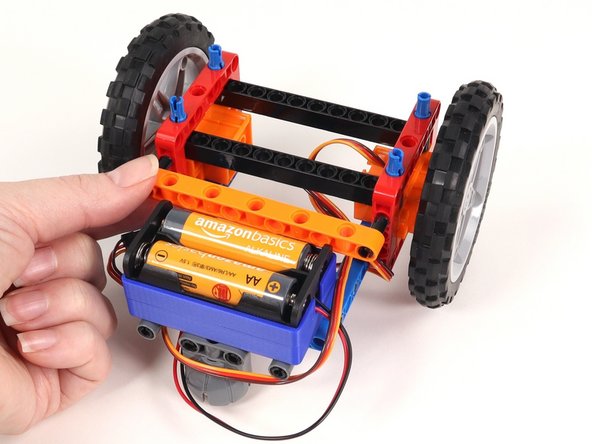
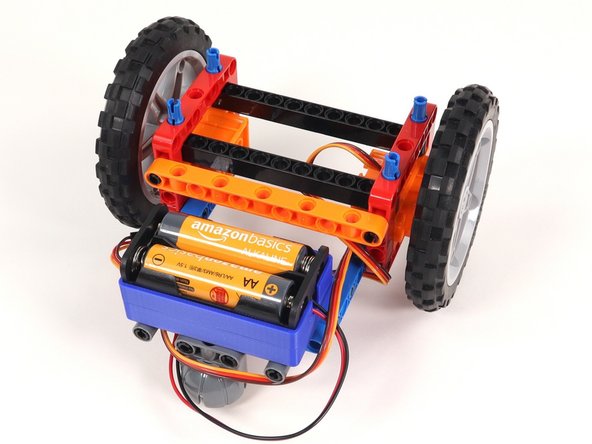
Add the orange beam to the back of the Rover. The black pins should go in the top holes of the red frames.
-
-
-
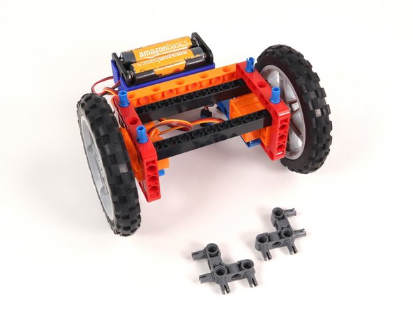
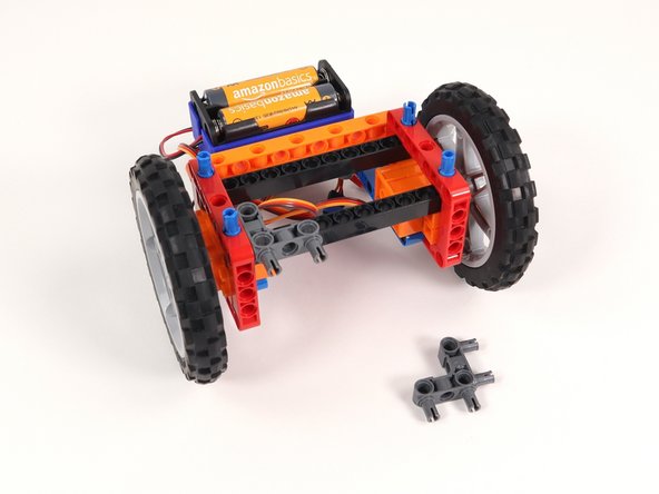
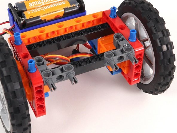
Add two gray 90° connectors to the Rover as shown. One side should connect to the inside of a red frame and the other pins should stick out towards the front of the Rover.
-
-
-
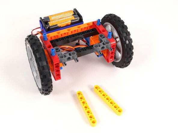
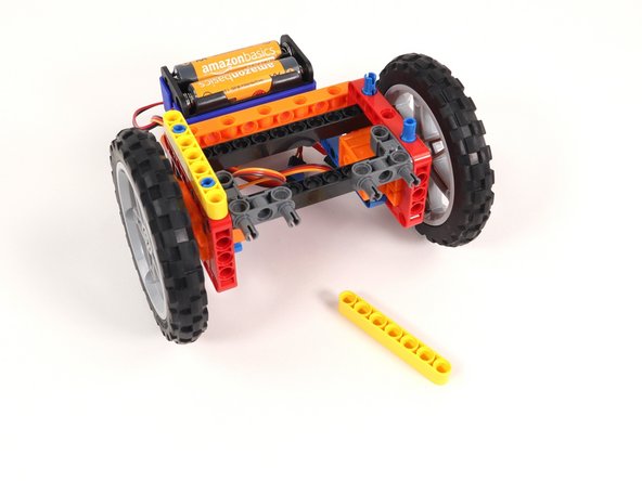
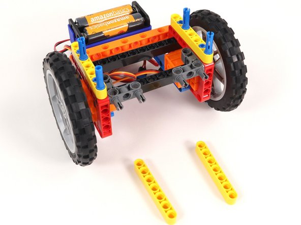
Add a yellow beam onto the blue pins on each side of the Rover
-
-
-
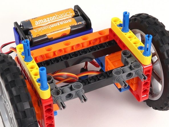
Add four blue pins into the yellow beams as shown.
-
The long pins should go in 1/3rd of the way, so make sure you have the orientation correct. (2/3rds should stick out the top.)
-
-
-
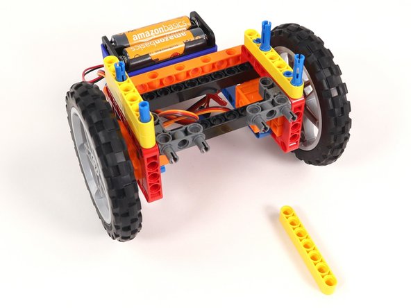
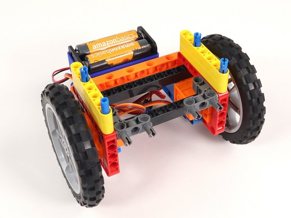
Add another yellow beam onto each set of blue pins.
-
Since 2/3rds of the blue pins are sticking out, you'll need to make sure to push the yellow beams down all the way so they are touching the other yellow beams. 1/3 of the blue pins should still be sticking out.
-
-
-
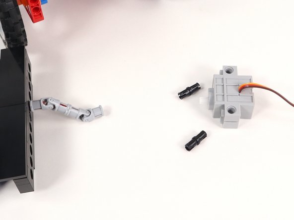
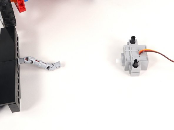
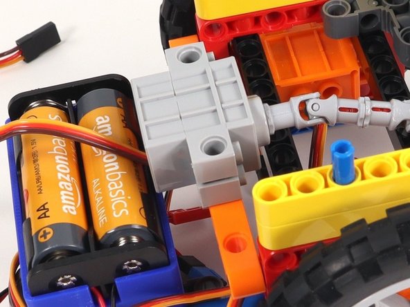
Insert two black pins into the servo on the side where the wires connect.
-
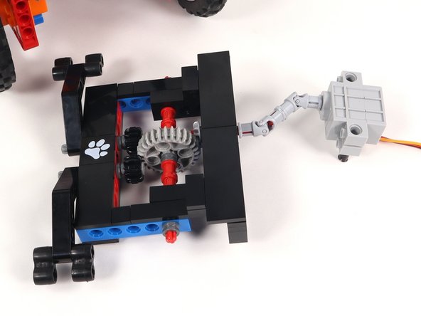
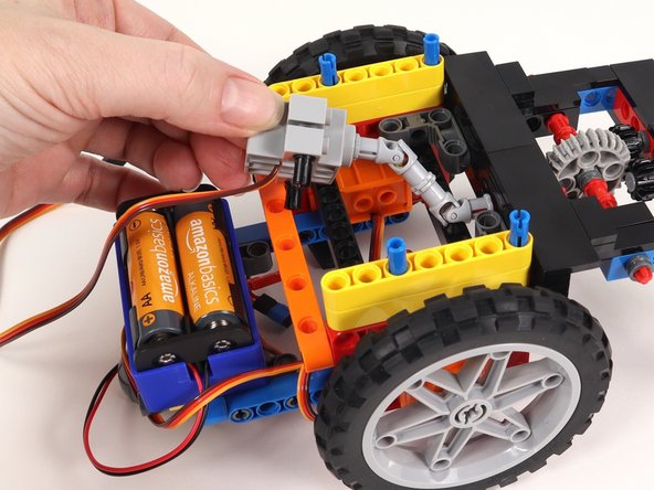
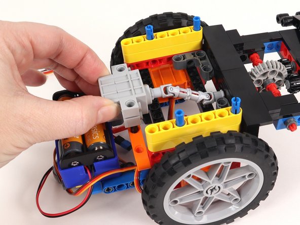
Connect the servo shaft to the universal joint on the Claw with the black pins and the wires facing down.
-
-
-
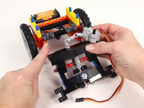
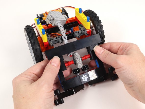
Connect the Claw to the front of the Rover to the gray 90° connectors by pressing it into place on the exposed pins.
-
-
-
Connect the two black pins on the servo to the orange beam with side holes on the back of the Rover. The wires should be facing the bottom of the Rover.
-
-
-
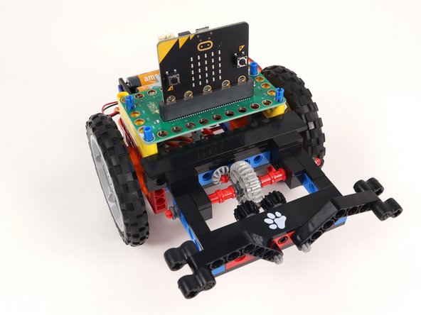
Add the Bit Board on top of the blue pins we added in Step 57.
-
Make sure the front of the Bit Board (and front of the micro:bit) are facing forward on the rover.
-
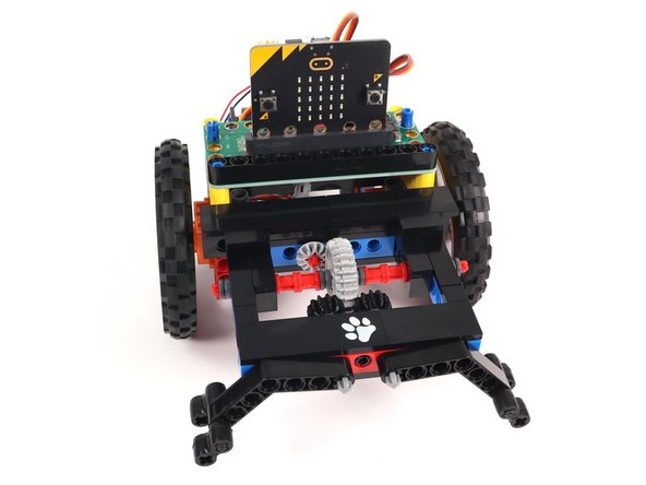
We'll reattach the long black beam onto the blue pins on the front of the Bit Board. This will help hold it securely in place.
-
Once the Bit Board is in place we can turn it around to the back so we can plug things back in.
-
-
-
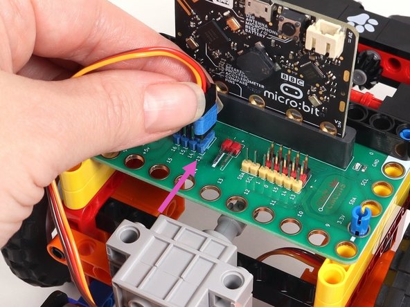
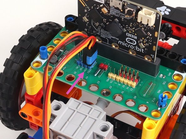
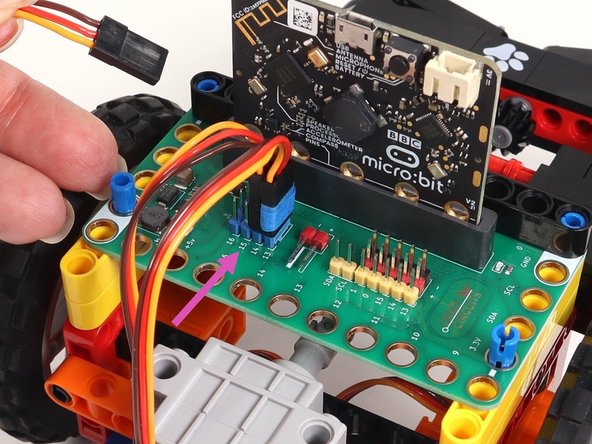
Plug the left servo connector into the row for Pin 13 of the blue 5V pins. The orange wire should go to the pin closest to the 13 on the board, the red wire goes into the +5v row, and the brown wire goes into the - row, which is ground.
-
Plug the right servo into the row for Pin 14 of the blue 5V pins, matching the orientation of the servo connector for the left servo.
-
Plug the gray servo connected to the Claw into the row for Pin 15 of the blue 5V pins, matching the orientation of the servo connector for the other servos.
-
The blue painters tape is there to help delineate the left and right servos. You do not need to add it.
-
-
-
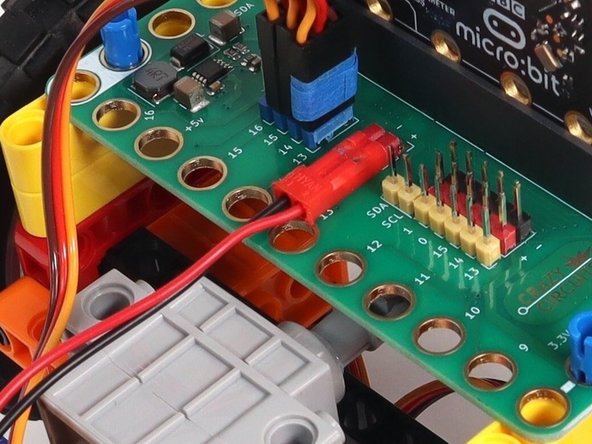
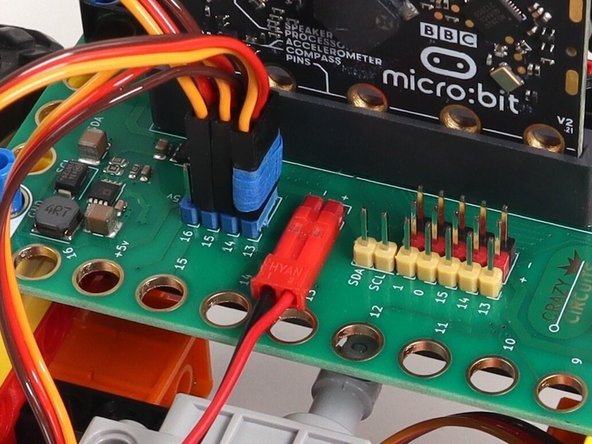
The last connection is the battery pack. It connects to the Bit Board as shown to provide power to the micro:bit and the servos so your rover can move.
-
-
-
Take a moment to double check your wiring.
-
Are the servo connectors oriented the right way? Hint: Make note of where the orange wire is.
-
Is the battery pack plugged in properly? The red wire should align with the + symbol behind the connector pins and you should see two metal pieces showing through slots in the red plastic housing.
-
If everything looks good, keep going!
-
-
-
If you've never used a micro:bit before you'll want to check out this guide: Bit Board V2 Setup and Use
-
We're going to load the following code for our Claw Test Code program: https://makecode.microbit.org/S63169-599...
-
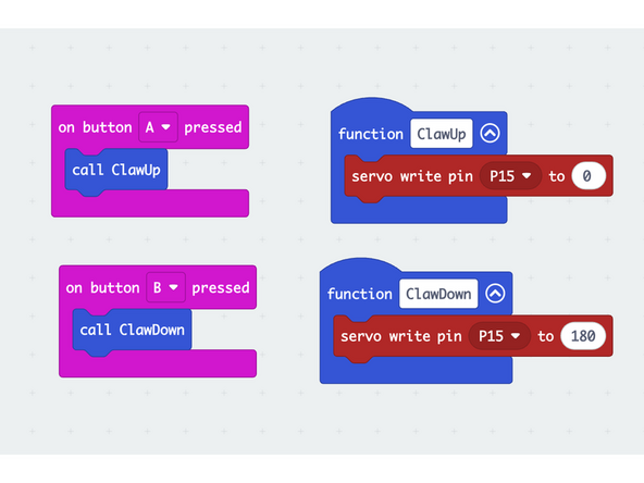
This code is very simple, and is just meant to test the Claw.
-
When you press the A button on the front of the micro:bit it should close and raise the Claw arms.
-
When you press the B button on the front of the micro:bit it should lower and open the Claw arms.
-
-
-
To test the Claw, power the Bit Board with the battery pack.
-
If the angles for your Claw arms aren't similar to the video, check out the next step for troubleshooting.
-
-
-
If, when you test out the Claw, the arms rotate all the way to the top and are not aligned properly follow these steps:
-
After pressing Button B, remove both arms from the axles.
-
Reattach the arms at the correct open angle as shown in the video.
-
-
-
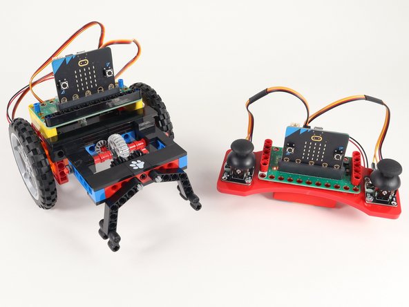
If you've got a Rover Thumbstick Remote you can use the following code to control the Rover and Claw
-
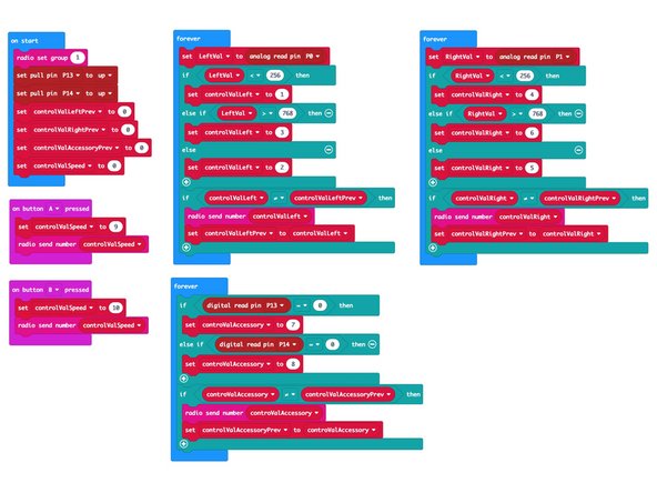
Load the following code: Rover Thumb Remote TX program to the micro:bit on the remote: https://makecode.microbit.org/S00082-291...
-
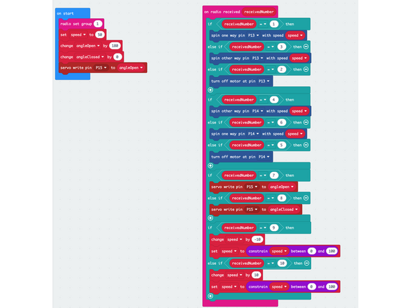
Load the code for the Rover Thumb Remote Claw RX onto the micro:bit on the Rover: https://makecode.microbit.org/S10511-326...
-
The TX stands for "Transmitter" which is the Remote. The RX stands for "Receiver" which is the Rover with the Claw.
-
Note that we've set the radio group to 1 on both micro:bits. You can choose any number you want as long as the two micro:bits use the same number. For a classroom setting with multiple pairs you'll want each set to have a different number.
-
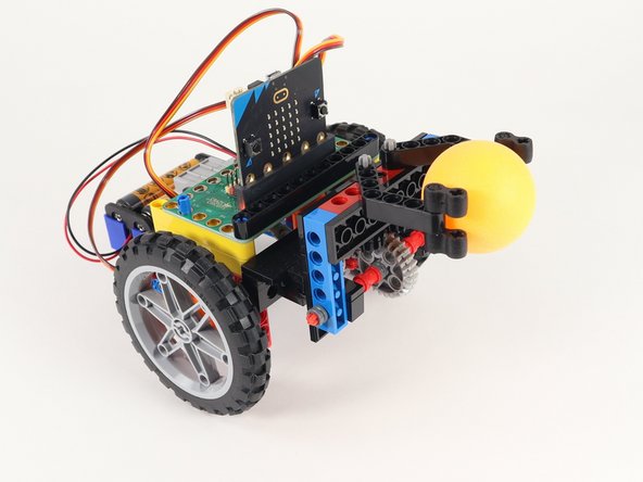
Once the code is loaded you can drive around your Rover and lift things!
-
-
-
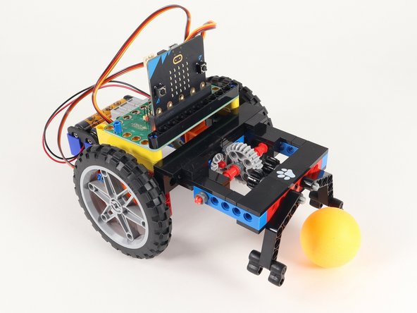
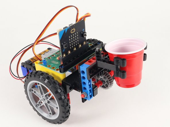
The Claw is a tricky attachment to use. It takes the right item and some practice to grab and lift an item successfully. We suggest ping pong balls or small cups as the first items you try to grab.
-
What else can you grab and lift? Can you print a 3D object that is easy to grab? Can you build something that won't fall out of the Claw when lifted? This takes quite a bit of trial and error to find just the right items!
-